Printer capable of cutting margins

a printing machine and cutting technology, applied in printing, printing mechanisms, manufacturing tools, etc., can solve the problems of reducing the size of the cutting device or printer, and no known thermal printer in which the margins would be appropriately cut away from the image recording region

Inactive Publication Date: 2002-06-25
FUJIFILM CORP +1
View PDF10 Cites 40 Cited by
  • Summary
  • Abstract
  • Description
  • Claims
  • Application Information

AI Technical Summary

Problems solved by technology

However, there is no known thermal printer in which the margins would be cut appropriately away from the image recording region.
This space causes the cutting device to h

Method used


Image

  • Printer capable of cutting margins
  • Printer capable of cutting margins
  • Printer capable of cutting margins

Examples


Embodiment Construction

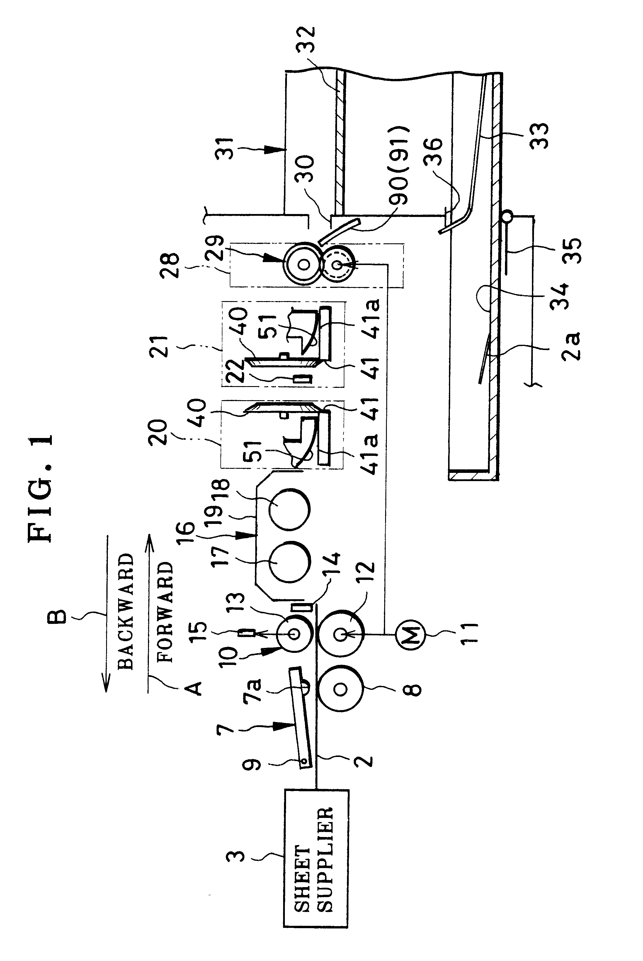
In FIG. 1, a color thermal printer is depicted. The thermal printer is used with color thermosensitive recording sheets 2 as recording material. A sheet supplier 3 contains the recording sheets 2 in a stack, and has a supply roller for supplying a body of the printer with the recording sheets 2.

A thermal head 7 and platen drum 8 are disposed downstream from the sheet supplier 3. A heating element array 7a is included in the thermal head 7, and has a great number of heating elements arranged in a line. A pivot 9 is a center about which the thermal head 7 is pivotally moved between a printing position and retracted position. The thermal head 7 presses the recording sheet 2 on the platen drum 8 when in the printing position, and comes away from the platen drum 8 when in the retracted position.

The recording sheet 2 includes a support, on which cyan, magenta and yellow coloring layers are overlaid as is well-known in the art. The yellow coloring layer is the farthest from the support, an...


PUM

PropertyMeasurementUnit
Timeaaaaaaaaaa
Thicknessaaaaaaaaaa
Diameteraaaaaaaaaa

Abstract

A color thermosensitive recording sheet extends two-dimensionally in main and sub scan directions perpendicular to each other. In a thermal printer for use with the recording sheet, two cutters remove front and rear margins from the recording sheet by cutting the recording sheet along lines extending in the main scan direction. Two slitters remove first and second side margins from the recording sheet by slitting the recording sheet along lines extending in the sub scan direction. A slitter shifter shifts the slitters in the main scan direction between a slitting position and home position. The slitters are set at the side margins when in the slitting position, and away from the recording sheet when in the home position. An externally operable mode selector selectively sets a marginless mode and margin mode. A controller causes the slitter shifter to shift the slitters to the slitting position when the marginless mode is set, and actuates the cutters and slitters. The controller causes the slitter shifter to shift the slitters to the home position when the margin mode is set, and disables the cutters and slitters.

Description

1. Field of the InventionThe present invention relates to a printer capable of cutting margins. More particularly, the present invention relates to a printer in which a front margin, a rear margin and side margins can be cut away from an image recording region in a print, and in which a space for containing a blade shifting mechanism is saved.2. Description Related to the Prior ArtA color thermal printer includes one thermal head. A thermosensitive recording sheet is fed in forward and backward directions, while the thermal head records three-color images according to the three-color frame-sequential recording.The thermal printer includes a feeder constituted by a capstan roller and pinch roller. The feeder nips the recording sheet and rotates to feed the recording sheet in forward and backward directions. While the recording sheet is fed in either of the directions, a thermal head thermally records the image of a particular one of the colors to the recording sheet. To stabilize the...

Claims


Application Information

Patent Timeline
IPC IPC(8): B26D1/01B41J11/70B41J11/68B41J11/66B26D1/24B26D1/20B26D7/22B26D5/32B26D7/24B26D5/20B26D7/00B26D9/00B26D5/02B41J11/00
CPCB26D1/205B26D1/245B26D5/02B26D5/32B41J11/706B26D7/24B26D9/00B41J11/0065B41J11/68B26D7/22Y10T83/7868Y10T83/8822
Inventor GOTO, SATORUKAYA, AKIMASA
Owner FUJIFILM CORP
Why Eureka
Try Eureka