Suspension frame construction

a frame and suspension technology, applied in the direction of steering linkages, pivoted suspension arms, transportation and packaging, etc., can solve the problems of low rigidity, disadvantageous driving stability and vibration noise, and achieve the effect of increasing rigidity

Inactive Publication Date: 2002-06-25
SUZUKI MOTOR CORP
View PDF3 Cites 41 Cited by
  • Summary
  • Abstract
  • Description
  • Claims
  • Application Information

AI Technical Summary

Benefits of technology

The present invention has been made to solve the above problems, and accordingly an object thereof is to provide a suspension frame construction capable of increasing rigidity when a braking load, a lateral load, or an engine mounting load is applied to a suspension frame.

Problems solved by technology

This lower arm mounting bracket 111, which is supported on the outside of the vehicle body mounting portions h, i and j in a cantilever manner, has a construction that provides low rigidity and is disadvantageous in terms of driving stability and vibration noise.

Method used


Image

  • Suspension frame construction
  • Suspension frame construction
  • Suspension frame construction

Examples


Embodiment Construction

Embodiments of the present invention will now be described in detail with reference to the accompanying drawings.

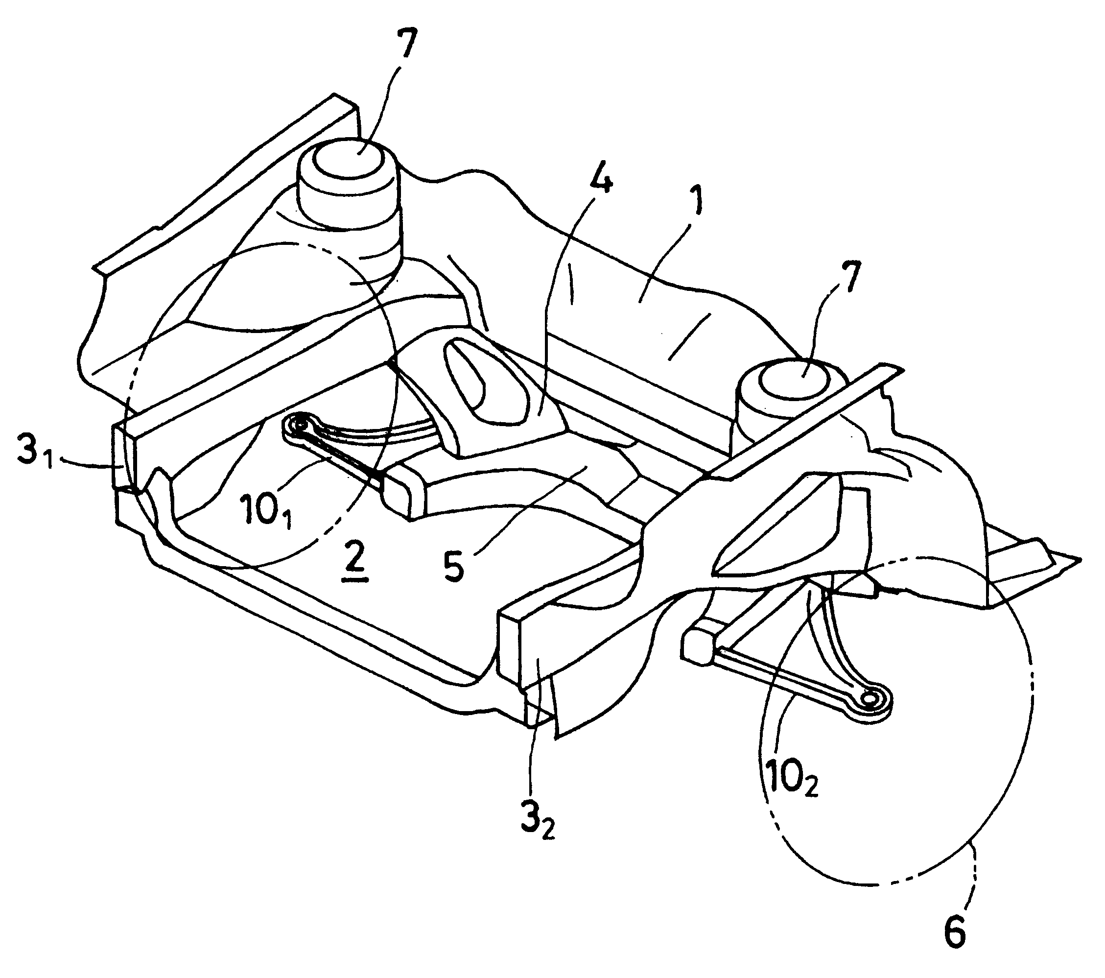
FIG. 1 shows the vehicle body front part of a motor vehicle.

In an engine room 2 isolated by a dash panel 1, a suspension frame 5 is installed to front side members 3.sub.1 and 3.sub.2, which are disposed on both sides of a vehicle body, via brackets 4 on the lower face side of the engine room 2. On the outside of the front side members 3.sub.1 and 3.sub.2 are provided struts 7 for suspending right and left wheels 6.

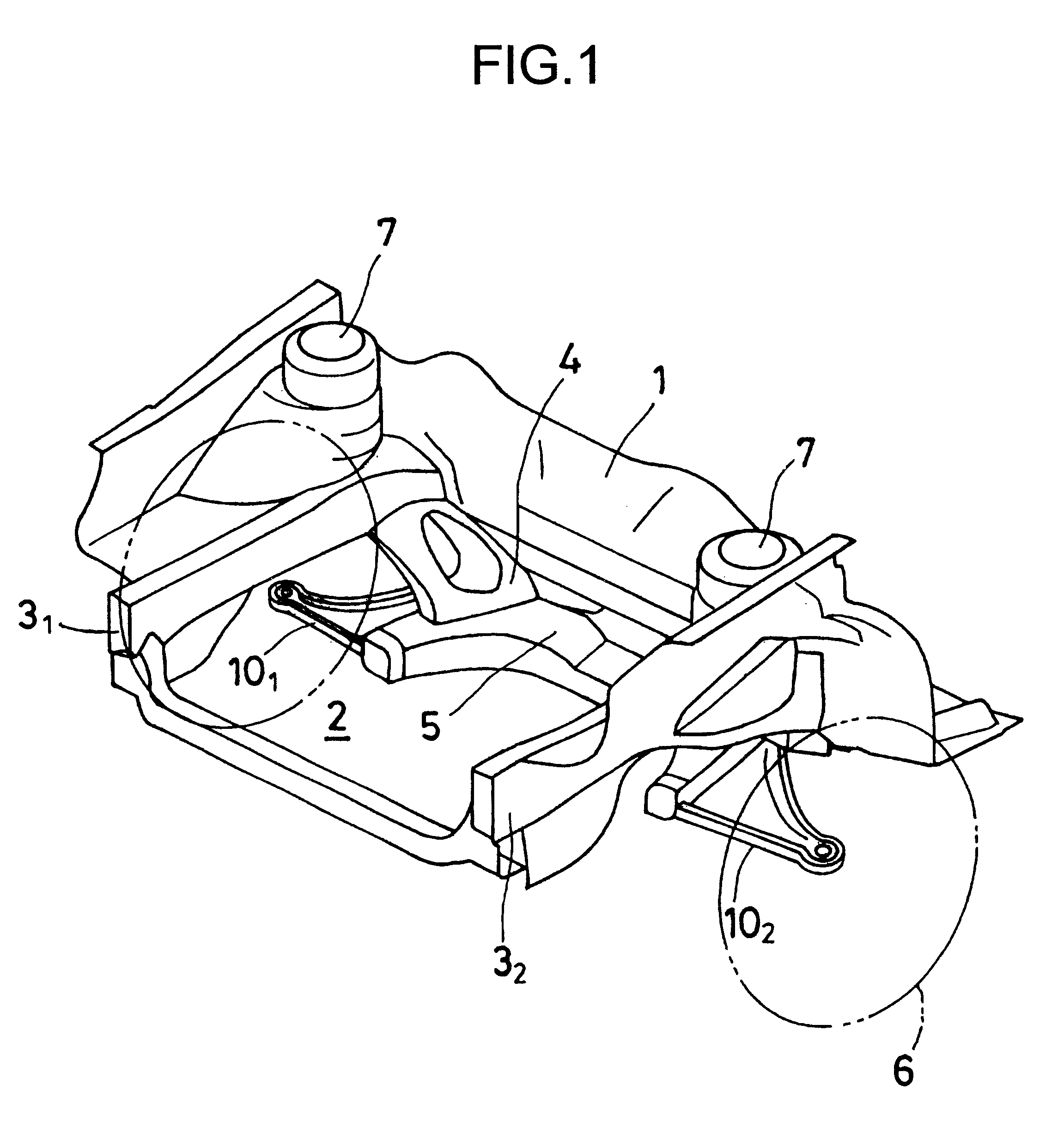
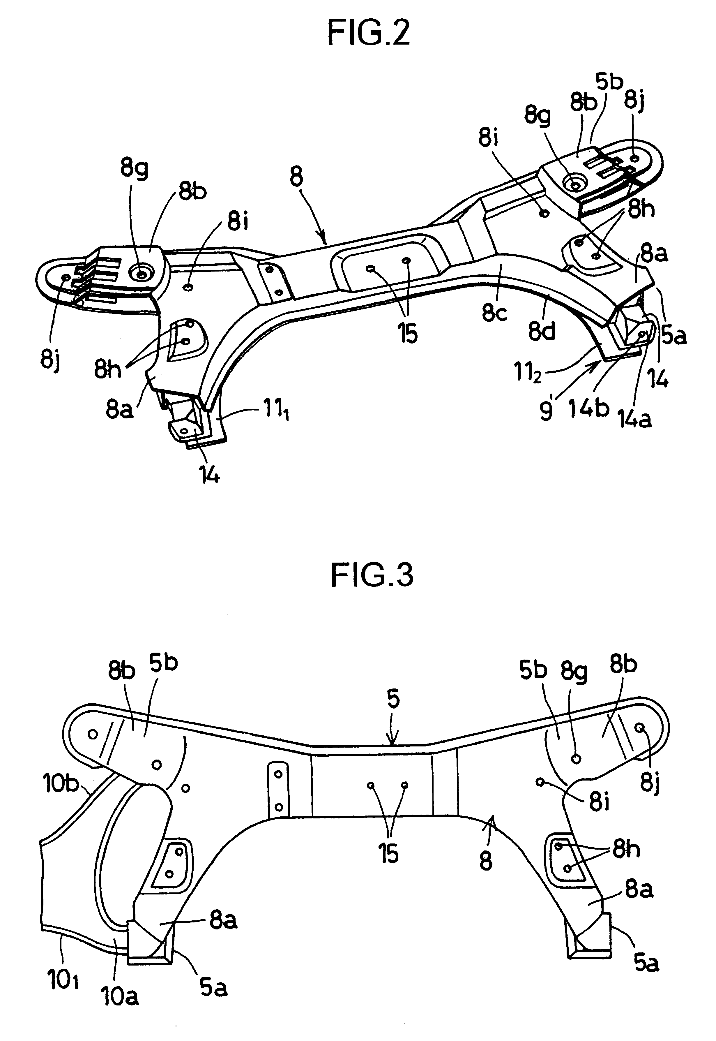
The construction of the suspension frame 5 will be described with reference to FIGS. 2 to 9.

As shown in FIGS. 2 to 6, the suspension frame 5 is formed into a substantially closed curved surface construction by joining an upper plate 8 and a lower plate 9', which are formed by pressing, to each other by welding or other means.

For the upper plate 8, as shown in FIGS. 2 to 4, the front and rear end portions of a flat steel plate are bent and extend downward, and s...


PUM


Abstract

There is provided a suspension frame construction capable of increasing rigidity when a braking load, a lateral load, or an engine mounting load is applied to a suspension frame. In a suspension frame construction comprising an upper plate and a lower plate joined to each other to form a suspension frame; and front- and rear-side suspension arm support portions provided at both ends, right and left, of the suspension frame, the lower plate 9 is made up of a pair of side plates 111 and 112 each provided with a support portion for supporting at least a rear-side arm of a suspension arm 101, 102 and a center plate 12 for connecting the side plates 111 and 112 to each other.

Description

FIELD OF THE INVENTION AND RELATED ART STATEMENTThe present invention relates to a suspension frame construction for supporting a suspension lower arm, an engine mounting member, and the like.Generally, the vehicle body constructions of motor vehicles are broadly divided into a framed construction used for motor trucks and the like and a frameless construction used for passenger cars and the like. The frameless construction incorporates side members and cross members as a part of body in place of a frame to increase the torsional rigidity. A chassis part is usually attached directly to the body, but, on some vehicles, it is attached to a partial frame, what is called a subframe, and then is assembled to the body.The subframe is also referred to as a suspension frame because suspension lower arms are usually attached to both sides of the subframe. Hereafter, the subframe and the like are given a general name of a suspension frame.The suspension frame is assembled to the vehicle body ...

Claims


Application Information

Patent Timeline
Patent Type & Authority Patents(United States)
IPC IPC(8): B60G7/02B62D21/11
CPCB60G7/02B60G2200/142B60G2206/60B60G2206/722B60G2206/8102B60G2206/82B62D21/11
Inventor SUZUKI, TOMOYUKI
Owner SUZUKI MOTOR CORP
Why Eureka
Try Eureka