System, program product and method of rendering a three dimensional image on a display

a three-dimensional image and display technology, applied in the field of image processing systems, can solve the problems of complex techniques that lead to substantial improvement in rendering time, inability to achieve tighter estimation of the visible set, and inability to achieve precise visibility computations

Inactive Publication Date: 2002-07-02
IBM CORP
View PDF2 Cites 16 Cited by
  • Summary
  • Abstract
  • Description
  • Claims
  • Application Information

AI Technical Summary

Problems solved by technology

In a given scene, {character pullout}, finding visible points or fragments that are connected to the eyepoint by a line segment that meets the closure of no other primitive within the same scene is a well known image processing problem.
Given the wide availability of the Z-buffer approach but with exact visibility computations potentially being too costly in terms of computer time and associated hardware costs, alternative approaches are being sought.
However, all of the above state of the art techniques for occlusion-culling have several drawbacks.
First of all, the simple backface and viewing-frustum culling algorithms of Foley et al. are unable to cull "overdraw" geometry.
For this type of culling, more comple

Method used


Image

  • System, program product and method of rendering a three dimensional image on a display
  • System, program product and method of rendering a three dimensional image on a display
  • System, program product and method of rendering a three dimensional image on a display

Examples


Embodiment Construction

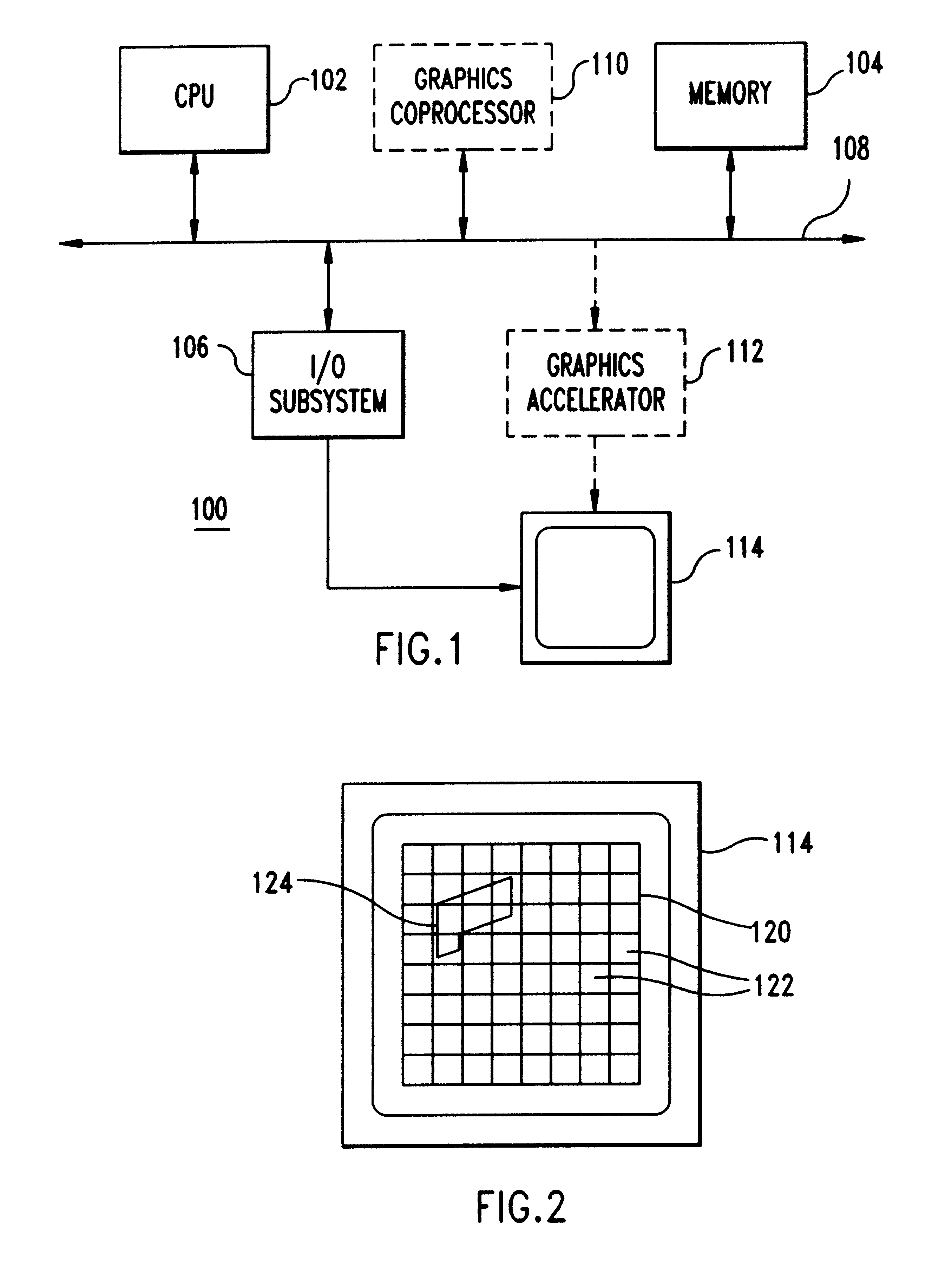
Referring now to the drawings, and more particularly, FIG. 1 is a block diagram of a preferred embodiment image processing system 100 that includes, as a minimum, a Central Processing Unit (CPU) 102, a memory subsystem 104 and an Input Output (I / O) subsystem 106 communicating through a data bus 108. Optionally, the system may include a graphics coprocessor 110 to offload graphics processing from the CPU 102, thereby reducing CPU computation-intensive tasks. Additionally, the preferred embodiment system 100 may include an optional graphics accelerator subsystem 112. Processed images are visualized on a display 114.

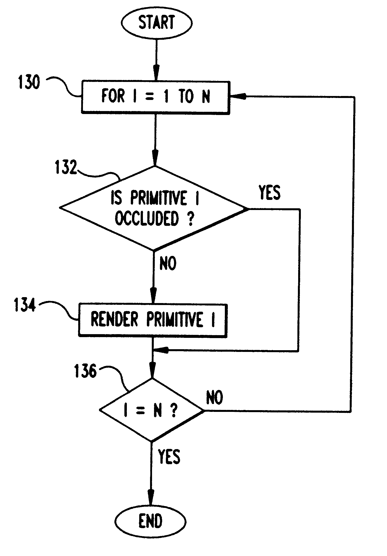
FIG. 2 is an example of an image rendered on display 114. The display area 120 is subdivided into display cells 122, normally referred to as pixels. A primitive 124, shown on the display 114, is a portion of the displayed three-dimensional scene. The primitive 124 is a projection of a three-dimensional primitive onto a two-dimensional "image space" of the display area 120. ...


PUM


Abstract

A Prioritized-Layered Projection (PLP) method and system for optimizing the rendering high-depth complexity scenes. Objects in each frame are prioritized with an estimation of the visible set within the rendered frame. A priority order for only the primitives in visible sets within the frame are computed "on demand" to maximize the likelihood of rendering visible primitives before rendering occluded ones. For a fixed budget, such as, time or number of triangles, rendering is constrained to a geometry budgeted priority. The method includes two main steps: an occupancy-based tessellation of space; and a solidity-based traversal algorithm. By first computing an occupancy-based tessellation of space, more cells result where there are more geometric primitives. In this spatial tessellation, each cell is assigned a "solidity" value directly proportional to its likelihood of occluding other cells. In its simplest form, a cell's solidity value is directly proportional to the number of primitives contained within the cell. Cells are marked for projection, and the geometric primitives contained within the marked cells are rendered. Cell solidity, and other view-dependent information determines the order cells are rendered.

Description

1. Field of the InventionThe present invention generally relates to image processing systems and, more particularly, to image processing systems capable of finding visible points or fragments that are connected by a line segment to the eyepoint that meets the closure of no other primitive within the same scene.2. Background DescriptionIn a given scene, {character pullout}, finding visible points or fragments that are connected to the eyepoint by a line segment that meets the closure of no other primitive within the same scene is a well known image processing problem. This visibility problem is discussed by D. Dobkin and S. Teller "Computer Graphics," Handbook of Discrete and Computational Geometry, chapter 42, pages 779-96. CRC Press, Boca Raton, Fla., 1997 (hereinafter Dobkin).As described in Dobkin, the scene, {character pullout}, is composed of modeling primitives (e.g., triangles, or spheres), and a viewing frustum defining an eye position, a view direction, and a field of view....

Claims


Application Information

Patent Timeline
IPC IPC(8): G06T15/40G06T15/10G06T15/20
CPCG06T15/20G06T15/40
Inventor KLOSOWSKI, JAMES T.SILVA, CLAUDIO T.
Owner IBM CORP
Why Eureka
Try Eureka