Electronic circuit for tuning vibratory transducers

Inactive Publication Date: 2002-07-09
SYST MATERIAL HANDLING
View PDF8 Cites 14 Cited by
  • Summary
  • Abstract
  • Description
  • Claims
  • Application Information

AI Technical Summary

Problems solved by technology

Unfortunately, a transducer's resonance frequency will change with age and conditions of operation, including temperature and humidity.
Even were the tuning mechanism not sealed, however, manual tuning is a time-consuming and inefficient process.
These methods are generally suited to particular tr

Method used


Image

  • Electronic circuit for tuning vibratory transducers
  • Electronic circuit for tuning vibratory transducers
  • Electronic circuit for tuning vibratory transducers

Examples


Embodiment Construction

, below.

A preferred embodiment of the present invention is described in detail below with reference to the attached drawing figures, wherein:

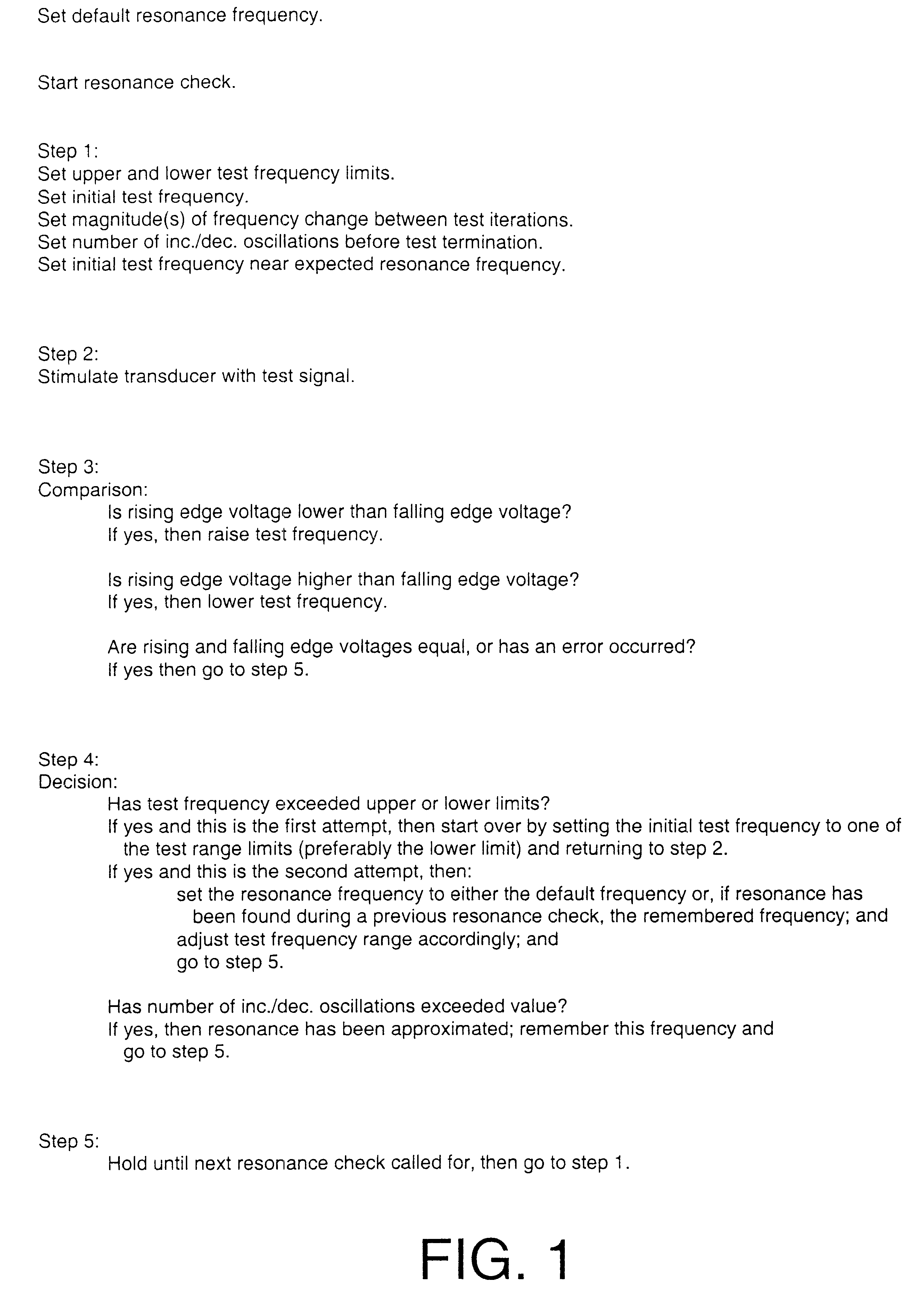
FIG. 1 is a flowchart illustrating the steps in a preferred embodiment of the method of the present invention.

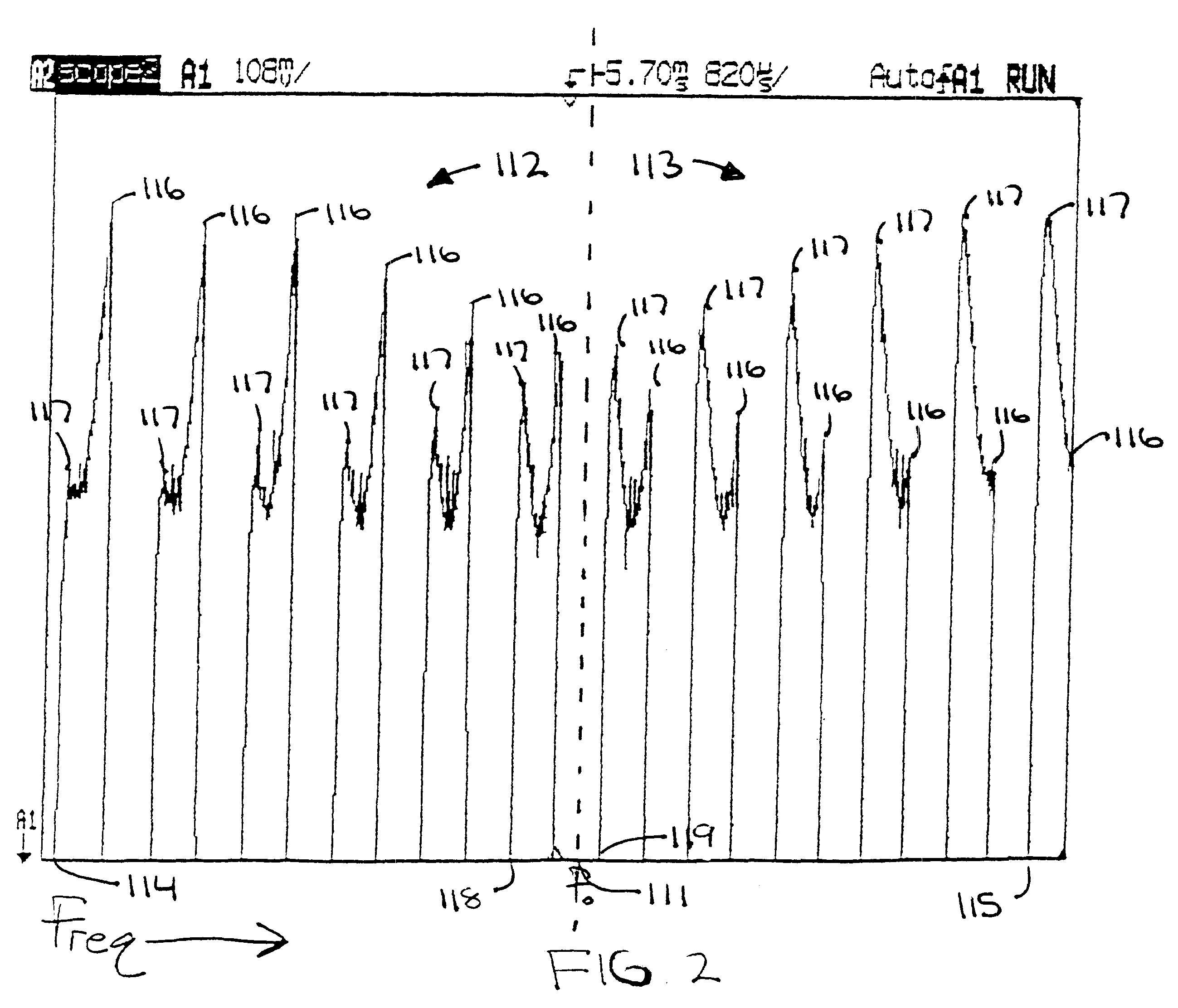
FIG. 2 is a waveform progression illustrating the relationship between resonance frequency and the rising and falling edge voltages of test waveforms.

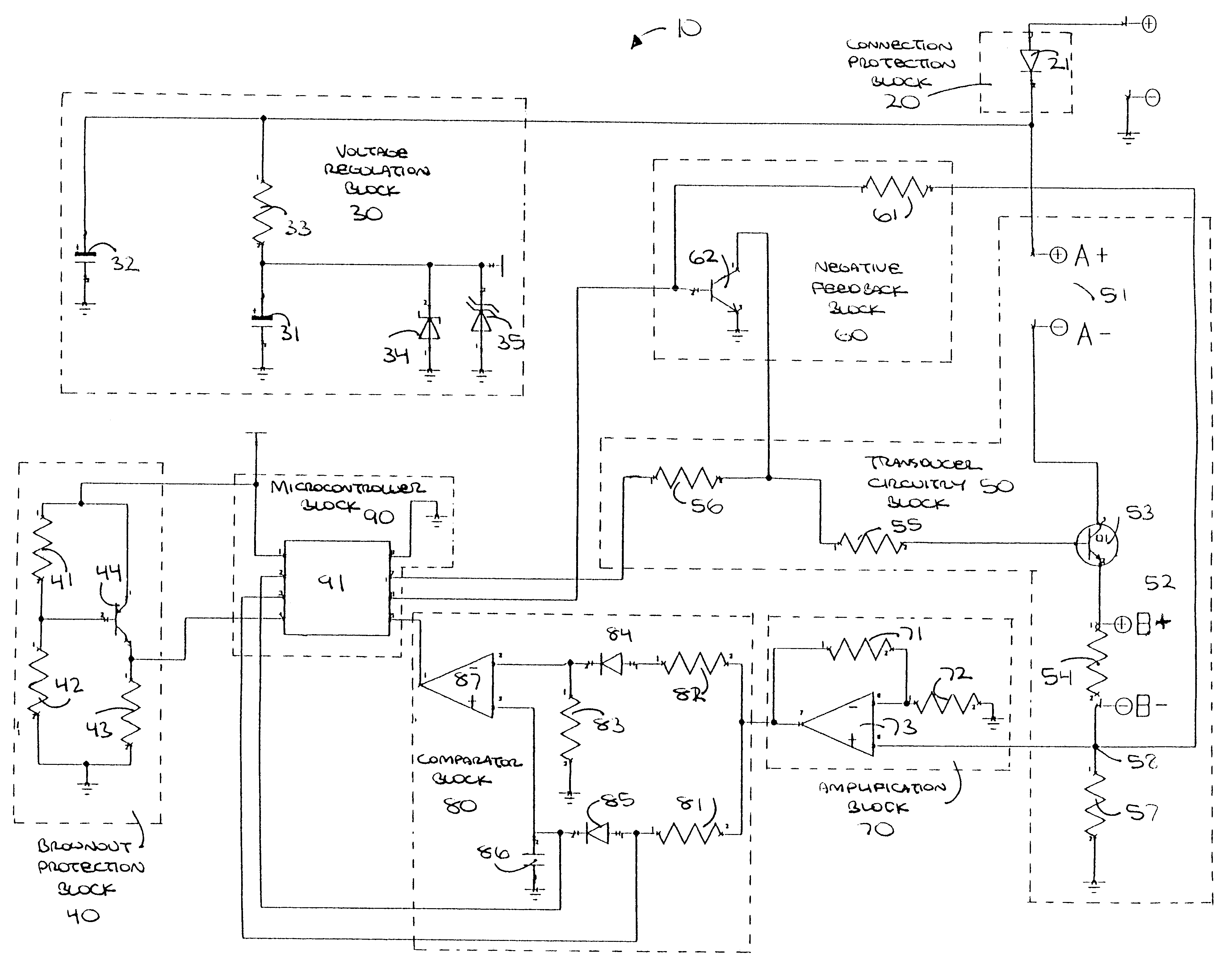
FIG. 3 is a block diagram superimposed over a detailed circuit schematic illustrating a tuning circuit constructed in accordance with a preferred embodiment of the present invention.

DETAILED DESCRIPTION OF A PREFERRED EMBODIMENT

1. The Method

Referring to FIG. 1, a flowchart is shown which illustrates a method of finding and maintaining the resonance frequency of a vibratory transducer. Such a method has application in maintaining peak efficiency and maximum performance in any vibratory transducer having the required waveform, including the speakers of common back-up alarms used on commercia...


PUM


Abstract

A method and self-tuning circuit for tuning vibratory transducers, broadly including electroacoustic speakers and specifically including the speakers of common back-up alarms used for safety reasons on commercial vehicles and heavy equipment. The self-tuning circuit is physically coupled to the transducer's input terminals and operates by comparing the rising and falling edges of one period of a test waveform elicited from the transducer by the application of a test signal having a test frequency. Depending on the results of this comparison, the test frequency is adjusted by predetermined increments upward or downward until the transducer's resonance frequency has been tightly bracketed though not exactly pinpointed.

Description

1. Field of the InventionThe present invention relates to the tuning of vibratory transducers, and, more particularly, to the tuning of speakers, including the speakers used in back-up alarms typically found on commercial vehicles and mobile equipment.2. Description of the Prior ArtVibratory transducers are devices that convert electric energy to kinetic energy. The resultant motion may by employed for a variety of purposes, including sound generation. This energy conversion is most efficient when the transducer is operating at its resonance frequency. Each vibratory transducer has its own particular resonance frequency to which it must be tuned for peak efficiency and maximum performance.Vibratory transducers may be found, for example, in the speakers of back-up alarms which are coupled to commercial vehicles and other mobile equipment to warn passersby that the vehicle is operating in reverse. When activated, the back-up alarm generates a warning tone at a particular frequency. As...

Claims


Application Information

Patent Timeline
IPC IPC(8): H04R29/00
CPCH04R29/001
Inventor SCHROEDER, GARY
Owner SYST MATERIAL HANDLING
Why Eureka
Try Eureka