Piezoelectric touch probe

a touch probe and piezoelectric technology, applied in the field of touch probes, can solve the problems of touch probe systems depicted in the patent, the touch probe system will be very stiff and brittle, and the touch probe system will be very stiff and brittle, and the effect of causing breakage or inacceptable errors

Inactive Publication Date: 2004-03-23
QUALITY VISION INT
View PDF9 Cites 42 Cited by
  • Summary
  • Abstract
  • Description
  • Claims
  • Application Information

AI Technical Summary

Problems solved by technology

1) The instant Piezoelectric Touch Probe (PTP) uses a piezoelectric driver to vibrate a high sensitivity accelerometer that is coupled to a stylus / suspension unit. Acceleration, not current, is used to detect contact conditions. Both the piezoelectric driver and accelerometer can be designed for high amplitude drive and resonant detection.
2) The stylus / suspension unit are flexible permitting significant deflection without taking on a permanent set. Stylus / suspension units are made from low modulus, high yield spring material. The stylus / suspension unit maintains the accuracy of CMM measurements by deflecting away from the part without causing bending of the part. The stylus / suspension unit is designed with a globe stiffness. This means that contact angle between a part and stylus does not significantly change interface stiffness.
3) The stylus / suspension unit vibrates using a transverse-mode and / or axial-mode of vibration at a high modal frequency (typically >=5th mode of transverse / axial vibration). This technique sensitizes the entire stylus shaft. Sensitizing the entire stylus shaft reduces shaft-out problems that occur when the CMM conducts a search for points that define the surface. Errors in measured points can result in shanking of the stylus during a measurement process. Shanking occurs when the stylus shaft, not the ruby tip, makes direct contact with the part. CMM software uses all data points including shank touches to locate the calibration points.
Due to this design, the touch probe system depicted in the patent will be very stiff and very brittle.
The stylus would not flex when making contact with a part, thus breakage or unacceptable error would likely occur.
Additionally, breakage of either the probe or the workpiece may well occur at high impact (touch) speeds.

Method used


Image

  • Piezoelectric touch probe
  • Piezoelectric touch probe
  • Piezoelectric touch probe

Examples


Embodiment Construction

)

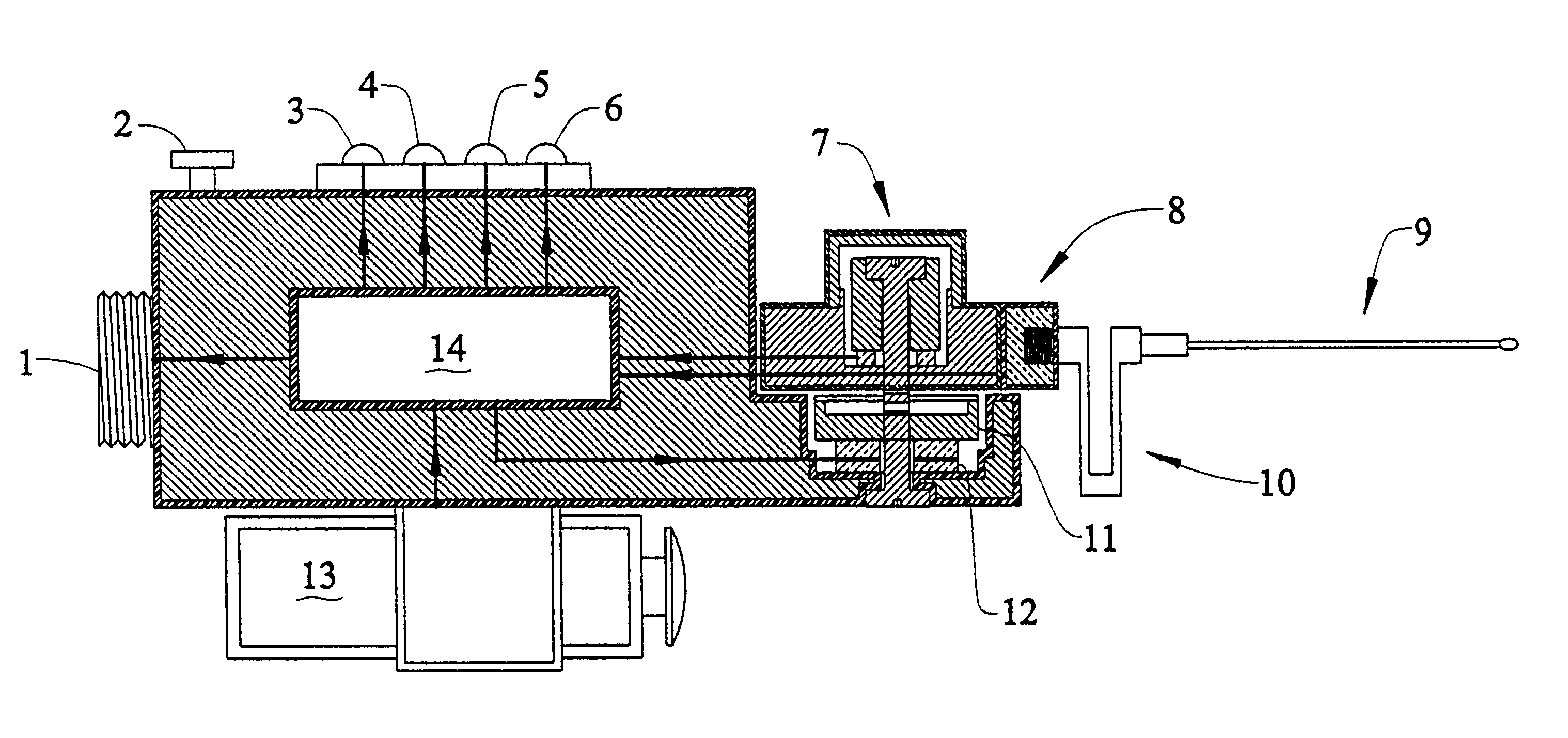
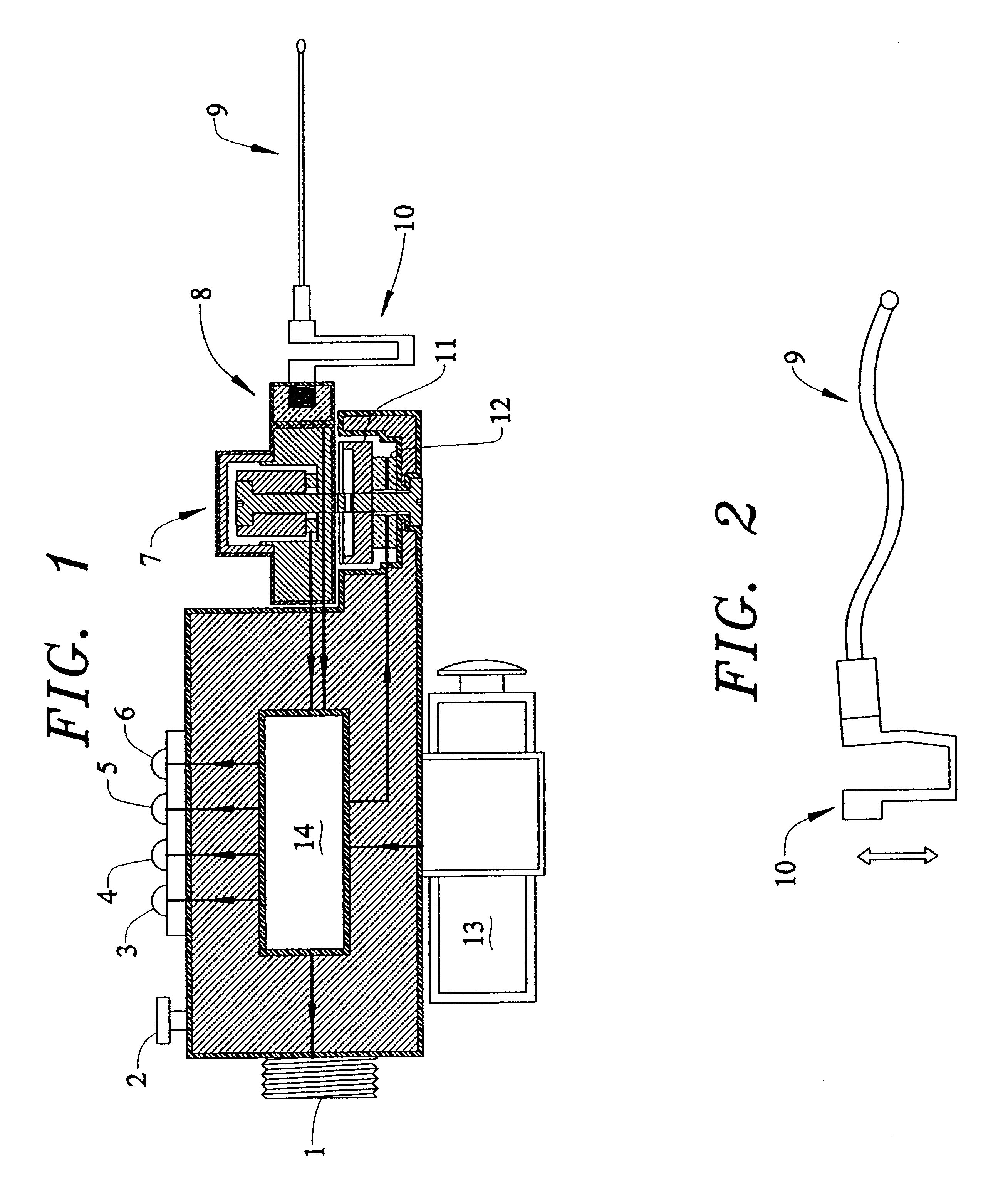
The Piezoelectric Touch Probe (PTP) of the present invention is a self-powered retrofit probe that is compatible with RENISHAW motorized probe heads. The mechanical and electrical interface for the PTP is a standard connection used to attach a RENISHAW touch probe to the motorized probe head. The invention will now be described with reference to the accompanying figures wherein like reference numerals indicate like parts.

With reference to FIG. 1, the Piezoelectric Touch Probe (PTP) consists of fourteen basic components. The threaded connector 1 couples the PTP to the RENISHAW motorized head either directly or through an extension / adaptor such as the RENISHAW autojoint, or the like. When detecting a touch event, the PTP produces a trigger signal to activate the RENISHAW control system and stop the CMM movement to collect position data. This trigger signal is similar, if not identical, to the output signal produced by RENISHAW touch probes.

The PTP is self-powered using a DC battery 1...


PUM


Abstract

The instant invention is a dynamic piezoelectric touch probe for use with coordinate measurement machines. The touch probe is characterized by five subsystems; (1) piezoelectric vibrator controlled by a self-tuning drive circuit that adjusts operating frequency and amplitude, (2) a high sensitivity, resonant accelerometer unit coupled to the piezoelectric vibrator, (3) a flexible suspension / stylus with transverse resonant frequencies tuned to the operating frequency band of the piezoelectric vibrator, (4) a digital control circuit that automatically sweeps the operating band of the piezoelectric vibrator to (a) detect the resonant frequency of the stylus / suspension, (b) set the drive signal frequency at the resonance of the stylus / suspension and (c) control the drive signal amplitude, and (5) a triaxial load cell system that is useful for detecting excessive low frequency suspension / stylus vibration, and excessive impact force during a touch event.

Description

This invention relates to touch probes useful in conjunction with coordinate measurement machines and particularly relates to piezoelectric touch probes.Touch probes are used by Coordinate Measurement Machines (CMM) to measure the geometry of structures. A typical multi-degree of freedom CMM consists of three hardware components:1) a robotic arm;2) a motorized probe head; and3) a touch probe.The robotic arm moves the probe head along the X, Y and Z axis. The motorized probe head rotates the touch probe in the vertical and horizontal planes. The use of a motorized probe head thus transforms a 3-axis CMM into a machine having 5 degrees of freedom. A workpiece with complex geometry including holes and cavities requires this capability. Utilizing position feedback and the touch sensitive probe, a CMM works by either tracing or interval touching a workpiece. Data collected by a CMM are used by engineers and manufacturers to document and qualify part geometry. A state-of-the-art CMM can b...

Claims


Application Information

Patent Timeline
Patent Type & Authority Patents(United States)
IPC IPC(8): G01B7/012G01B7/016G01B3/00G01B7/008
CPCG01B7/012
Inventor FLANAGAN, PATRICK M.
Owner QUALITY VISION INT
Why Eureka
Try Eureka