Video-monitoring safety systems and methods

a safety system and video monitoring technology, applied in the field of safety systems, can solve problems such as warning systems becoming obstructed in some manner, accidents continue to occur in these locations, and countries that pose a danger to drivers of vehicles

Inactive Publication Date: 2002-07-16
BBNT SOLUTIONS LLC
View PDF12 Cites 30 Cited by
  • Summary
  • Abstract
  • Description
  • Claims
  • Application Information

AI Technical Summary

Problems solved by technology

There are thousands of locations across the country that pose a danger to drivers of vehicles, such as cars, buses, trucks, trains, and the like.
Nevertheless, accidents continue to occur at these locations.
Drivers may enter the location at such excessive speeds that they cannot stop in time to avoid an obstacle in their course.
Alternatively,

Method used


Image

  • Video-monitoring safety systems and methods
  • Video-monitoring safety systems and methods
  • Video-monitoring safety systems and methods

Examples


Embodiment Construction

refers to the accompanying drawings. The same reference numbers in different drawings identify the same or similar elements. Also, the following detailed description does not limit the invention. Instead, the scope of the invention is defined by the appended claims and equivalents.

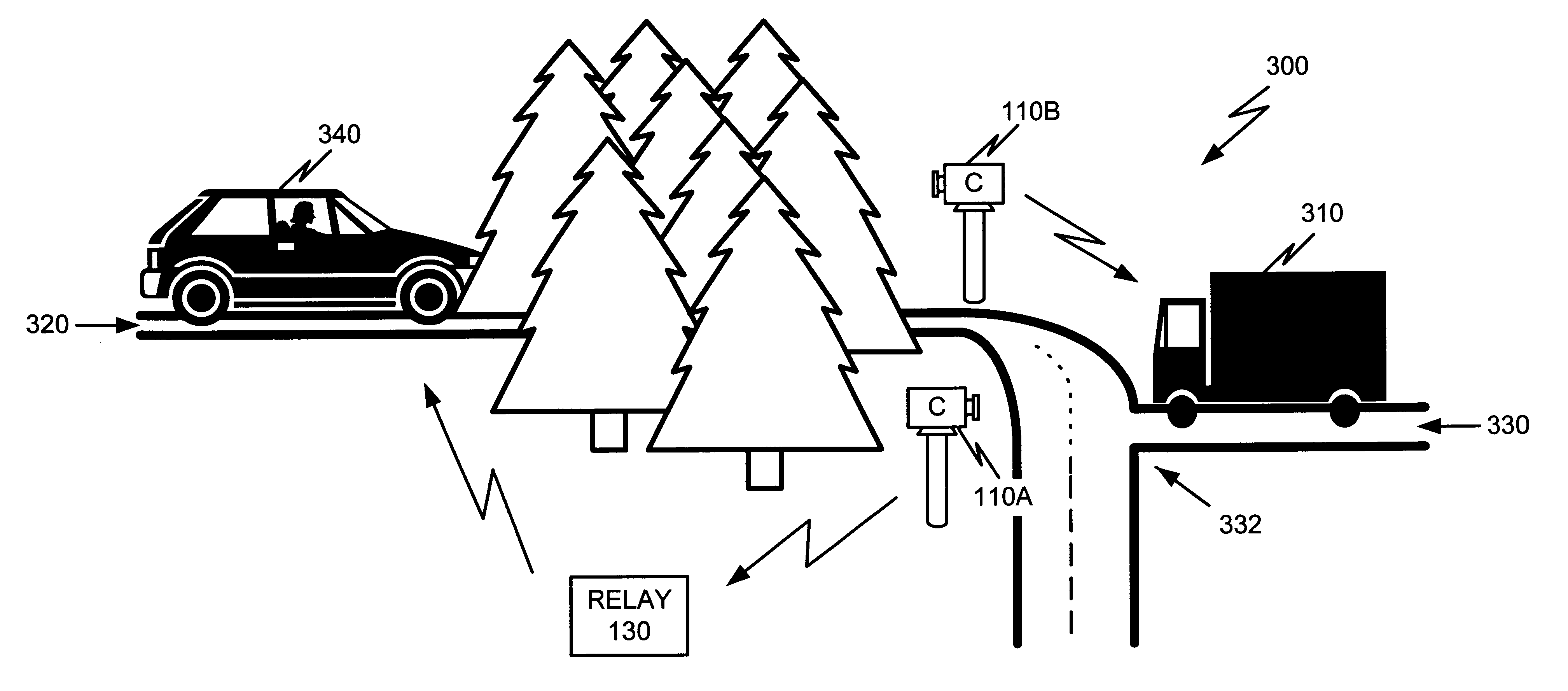
Systems and methods consistent with the present invention provide a simple and easily deployable mechanism that supplies early visual warnings to drivers of vehicles of actual dangers at various locations when the vehicles are in proximity to the locations to reduce the occurrence of accidents.

Exemplary System

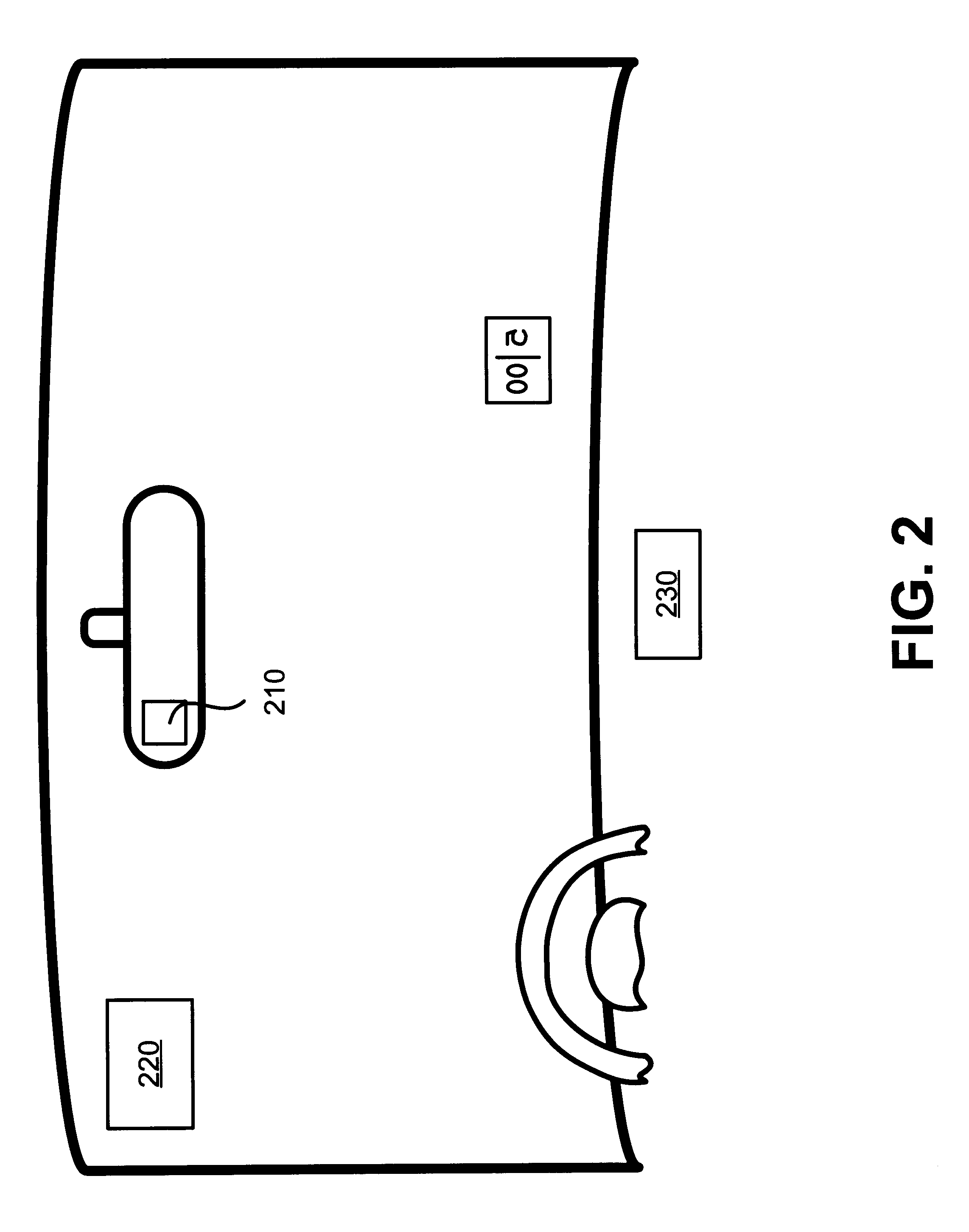
FIG. 1 is an exemplary diagram of a monitoring system 100 consistent with the present invention. The system 100 includes at least two separate components: a camera device 110 and a display device 120. The camera device 110 may be a stationary device located at a predetermined location. The camera device 110 includes a camera 112 and a transmitter 114. The camera 112 may include a conventional security...


PUM


Abstract

A system facilitates visual monitoring of a dangerous location. The system includes a stationary camera device (110) and at least one mobile display device (120) corresponding to at least one vehicle. The camera device (110) captures a video image of the dangerous location and transmits video signals representative of the captured video image. The display device (120) receives the video signals from the camera device (110) when the corresponding vehicle is in proximity to the camera device (110) and presents the video signals as a video image of the dangerous location to a driver of the vehicle.

Description

A. Field of the InventionThe present invention relates generally to safety systems and, more particularly, to systems and methods that present a simple and easily deployable mechanism that provides visual information regarding locations, such as dangerous intersections, blind comers or curves, railroad crossings, etc., to drivers of vehicles to reduce the occurrence of accidents.B. Description of Related ArtThere are thousands of locations across the country that pose a danger to drivers of vehicles, such as cars, buses, trucks, trains, and the like. Many of these locations contain warning signs, such as "Hidden Driveway," "Blind Curve," "Railroad Crossing," and the like, to warn drivers of the potential dangers. These locations may also contain some type of warning signal, such as a flashing light or an audible alarm. Nevertheless, accidents continue to occur at these locations.The reasons for the accidents vary. Drivers may enter the location at such excessive speeds that they can...

Claims


Application Information

Patent Timeline
IPC IPC(8): G08G1/16H04N7/18B61L29/00B61L29/24
CPCB61L29/00B61L29/246G08G1/164H04N7/183
Inventor CORBITT, TIMOTHY W.PASSMAN, WILLIAM S.
Owner BBNT SOLUTIONS LLC
Why Eureka
Try Eureka