Method of and a device for milking an animal

a technology for milking devices and animals, which is applied in the field of milking devices, can solve the problems of teat cup liners that are not available today, can not be used in milking devices, and can not be used in milking products

Inactive Publication Date: 2002-07-30
DELAVAL HLDG AB
View PDF9 Cites 9 Cited by
  • Summary
  • Abstract
  • Description
  • Claims
  • Application Information

AI Technical Summary

Problems solved by technology

In practice, such differences are not possible to avoid in teatcup liners available today by the manufacturing methods which are offered, i.e. any usual moulding method.
However, even if it is possible to manufacture a teatcup liner with an absolutely uniform wall thickness a weakening arises at each collapse occasion and because thereof such predetermined positions for the flexing folds will develop.
Due to the fact that the teatcup liner always collapses at the same location on the teat, there is a risk of injuries on the teat, ...

Method used


Image

  • Method of and a device for milking an animal
  • Method of and a device for milking an animal
  • Method of and a device for milking an animal

Examples


first embodiment

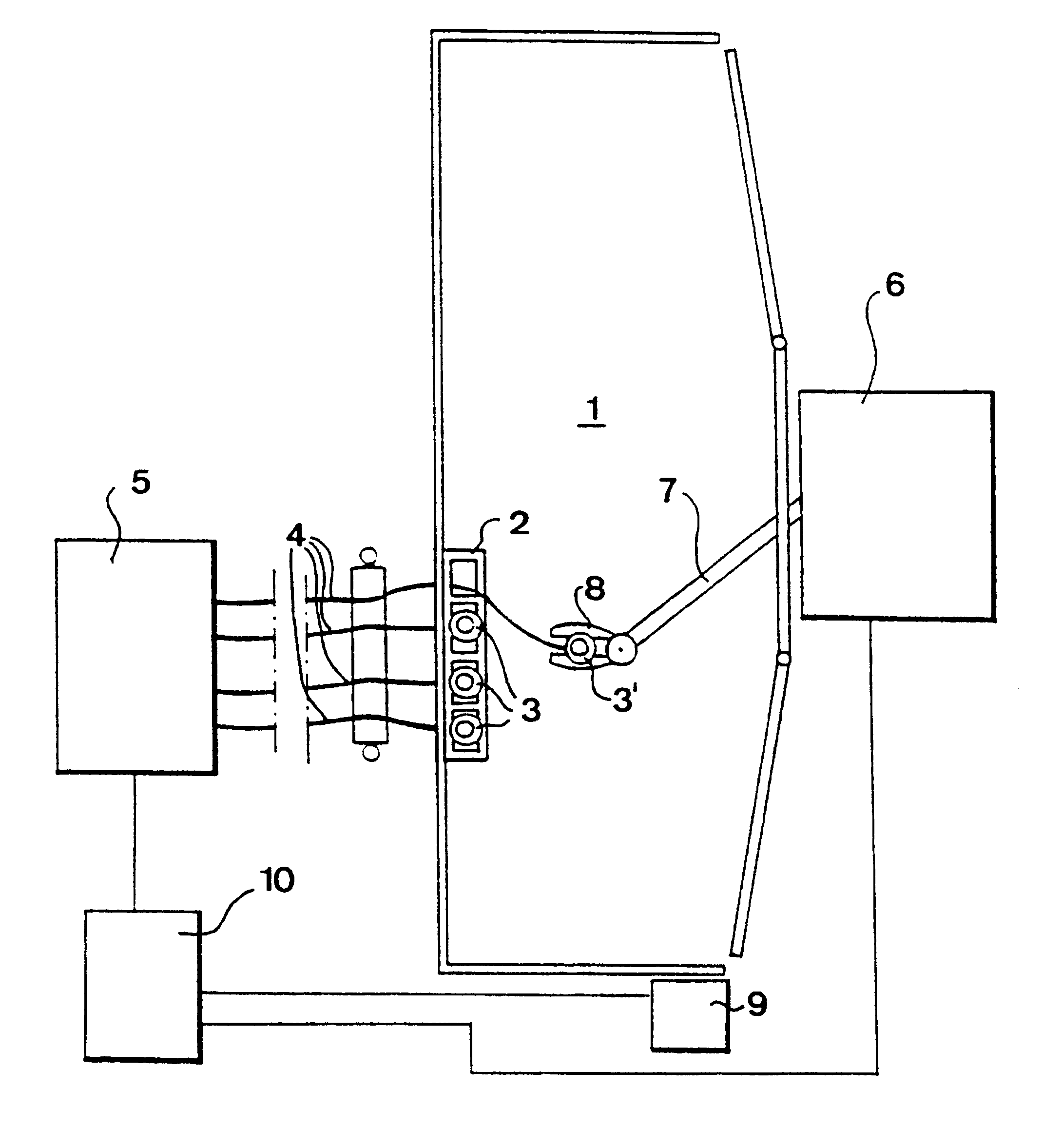
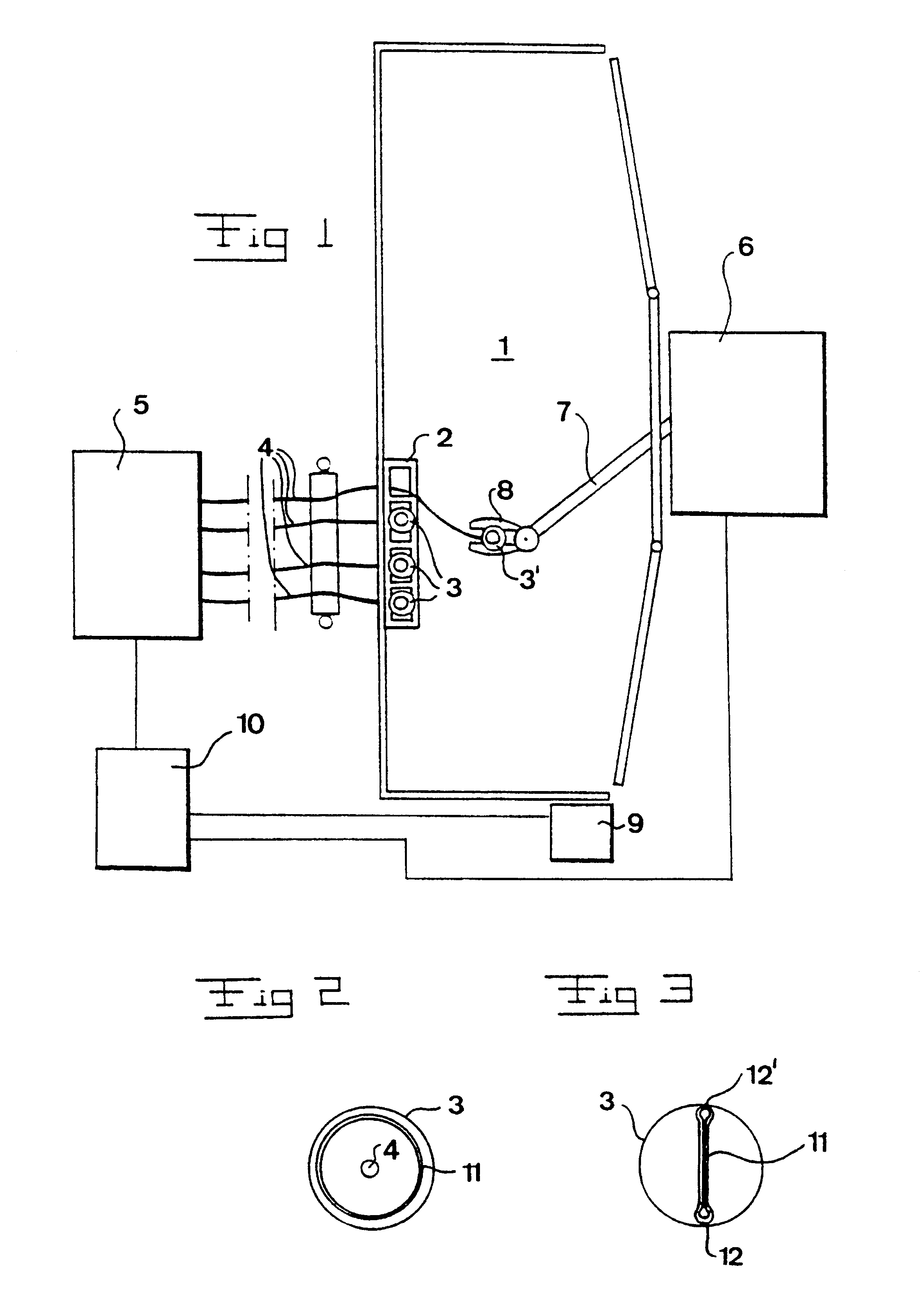
it is possible by the arrangement disclosed in FIG. 1 to obtain the first functional mode by applying a specific teatcup 3' by means of the milking robot 6 to a teat at the first milking occasion and applying said teatcup to another teat at the second milking occasion. Thereby, the teatcups 3 may be applied to the teats in a first order or succession at the first milking occasion and in a second order or succession at the second milking occasion. Here, the succession refers to the succession by which the teatcups 3 are engaged by means of the gripping member 8 from the teatcup magazine 2. Within the scope of the invention, it is of course also possible to engage the teatcups 3 from the teatcup magazine 2 in the same order but change the order by which the teatcups 3 are applied to the teats at different milking occasions. In both these cases, the succession at each milking occasion may be determined by means of the control unit 10. The cow which is present in the milking stall and i...

second embodiment

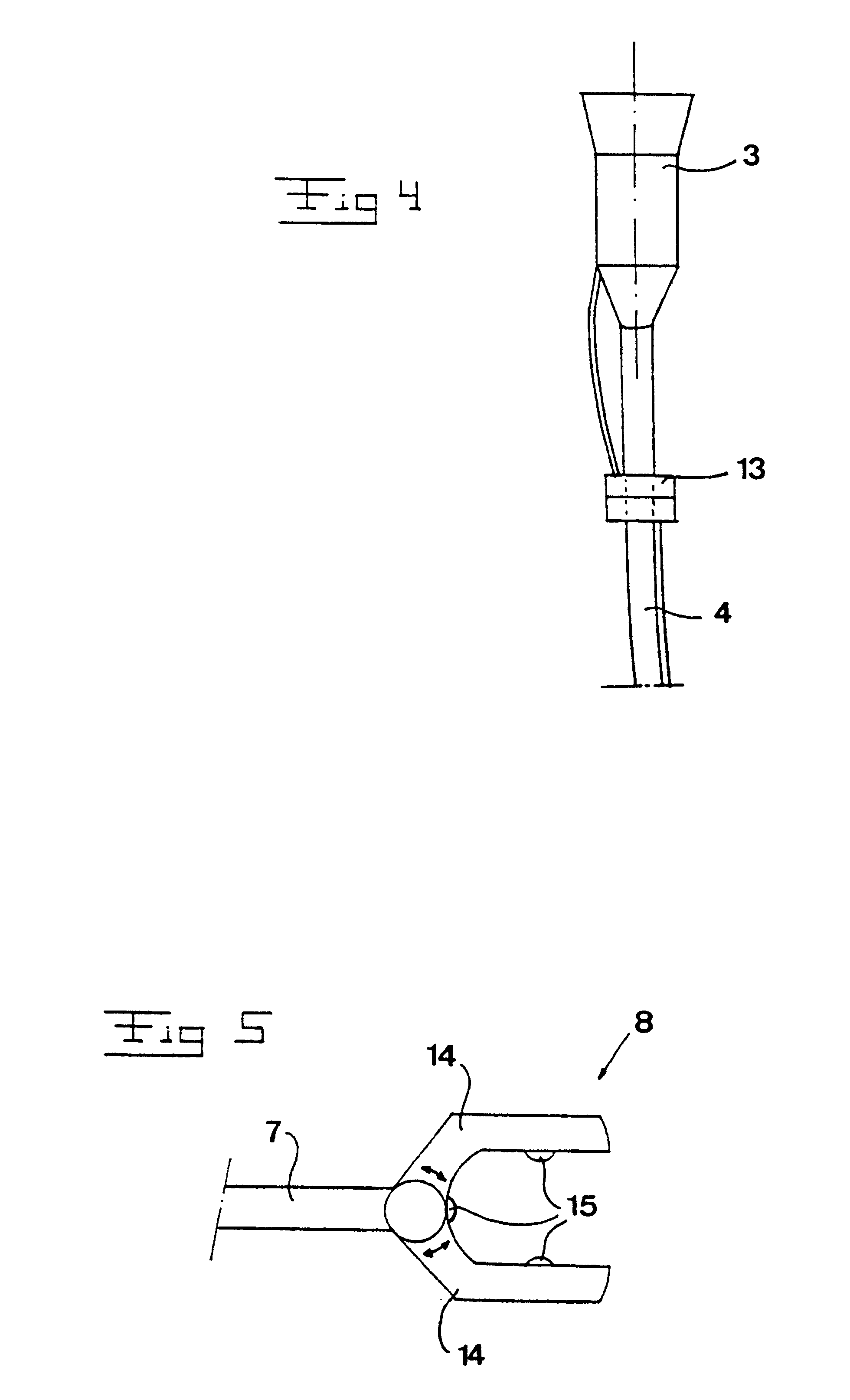
it is possible by the arrangement disclosed in FIG. 1 to obtain the second functional mode by rotating the teatcup 3, see FIG. 4, between the first milking occasion and the second milking occasion about a longitudinal centre axis x extending through the teatcup 3 in its longitudinal direction. Since the milk conduit 4 is relatively rigid with regard to a rotation, such a rotation of the teatcup 3 is facilitated by means of a swivel connection 13 permitting such a rotation. The swivel connection may be provided on the milk conduit 4, or between the milk conduit 4 and the teatcup 3 proper. The swivel connection 13 is, as appears of FIG. 4, advantageously designed in such a manner that it also permits rotation of the pulse conduit, wherein the pulse conduit and the milk conduit may form a common conduit bundle. The swivel connection 13 may thereby, for instance, comprise an inner passage for the milk and an outer chamber surrounding the inner passage and forming a passage for the pulse...

fifth embodiment

working according to the first functional mode, the conduit bundle 20 may be provided with a swivel connection 21 permitting the rotation of the teatcup claw 18, for instance a quarter of a round, between each milking occasion. Also in this case, it is possible to control the rotation by means of the control unit 10 in the manner which is described above but this embodiment is also applicable to manual or semiautomatic milking, i.e. in the cases that the teatcups 3 are applied manually to the teats of a cow.


PUM


Abstract

A method and device for milking an animal by using at least one milking machine (5) including at least one teatcup (3) having a teatcup liner (11) forming a space defined by a wall surface. The teatcup (3) is arranged to be applied to a teat in such a manner that the wall surface extends around and abuts the teat. The device includes a control unit arranged to control the application of the teatcup (3) in such a manner that an arbitrary portion of the wall surface abuts different teat portions during a first milking occasion with respect to an animal and during a later milking occasion with respect to this animal, respectively.

Description

1. Field of the InventionThe present invention refers to a method for milking an animal by means of at least one milking machine comprising at least one teatcup having a teatcup liner forming a space defined by a wall surface, the method comprising the step of applying said teatcup to a teat in such a manner that the wall surface extends around and abuts the teat. Moreover, the invention refers to a device for milking an animal by means of at least one milking machine comprising at least one teatcup having a teatcup liner forming a space defined by a wall surface, said teatcup being arranged to be applied to a teat in such a manner that the wall surface extends around and abuts the teat.2. Description of the Prior ArtThe teatcup liners which are provided in teatcups of such milking machines defined above are subjected to a pulsating movement due to the cyclically alternating pressure level prevailing in the pulsating chamber formed in the teatcup between the outer surface of the tea...

Claims


Application Information

Patent Timeline
IPC IPC(8): A01J5/00A01J5/017A01J5/08A01J5/007
CPCA01J5/007A01J5/0175A01J5/08
Inventor LIND, OLEBJORK, ANDERS
Owner DELAVAL HLDG AB
Why Eureka
Try Eureka