Suction roll seal strip with wear indicator

Inactive Publication Date: 2002-08-20
JOCELL
View PDF10 Cites 23 Cited by
  • Summary
  • Abstract
  • Description
  • Claims
  • Application Information

AI Technical Summary

Problems solved by technology

Since the paper machine is operating continuously, it may take several months before it is stopped for service, including checking of the seal strips which are being used.
The first case is uneconomical, since the seal strips are thrown away before their life time is finished and the second case is uneconomical since the efficiency of the suction roll decreases at operation with too worn seal strips.
The drawback of the seal strip

Method used


Image

  • Suction roll seal strip with wear indicator
  • Suction roll seal strip with wear indicator

Examples


Embodiment Construction

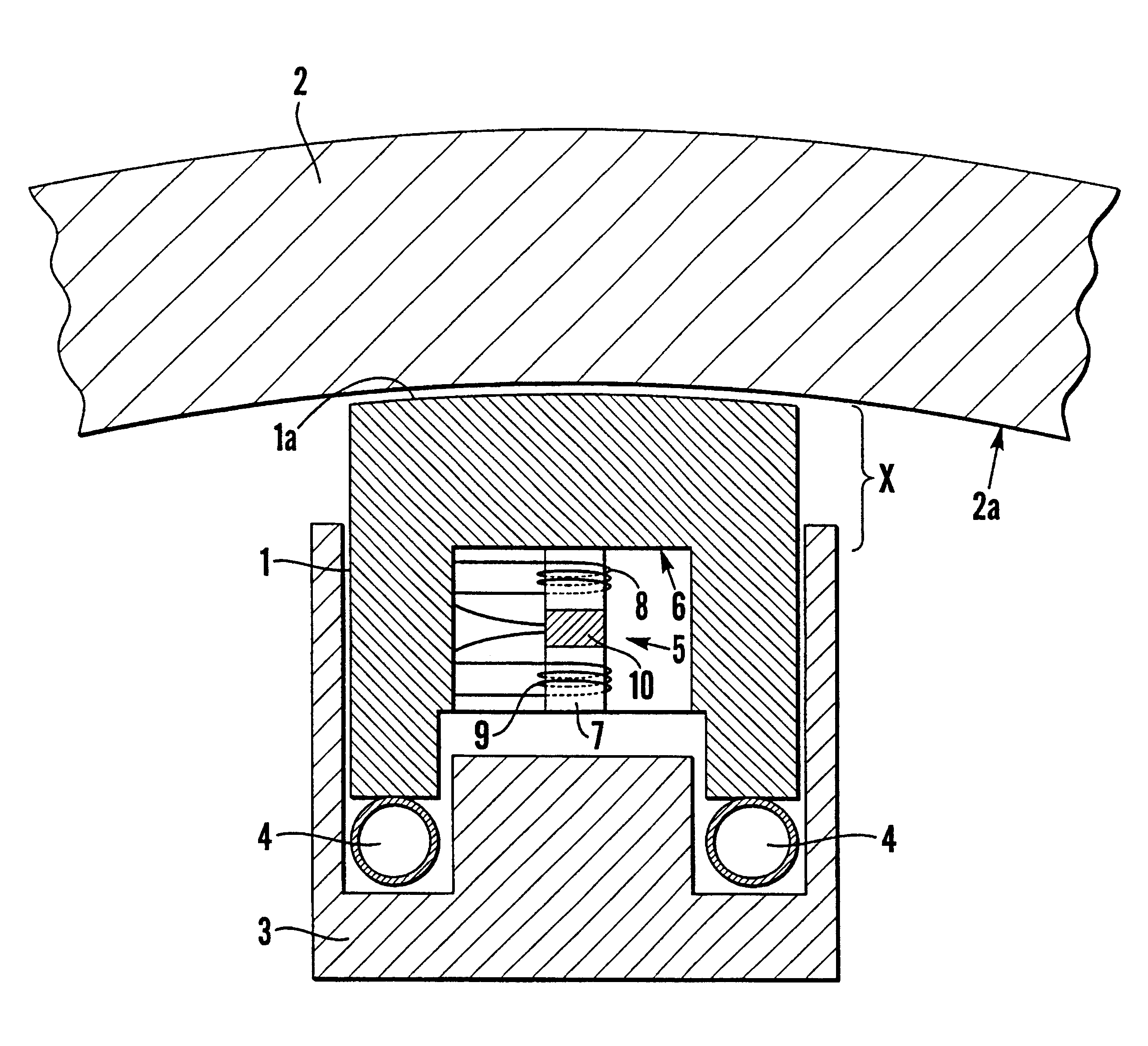
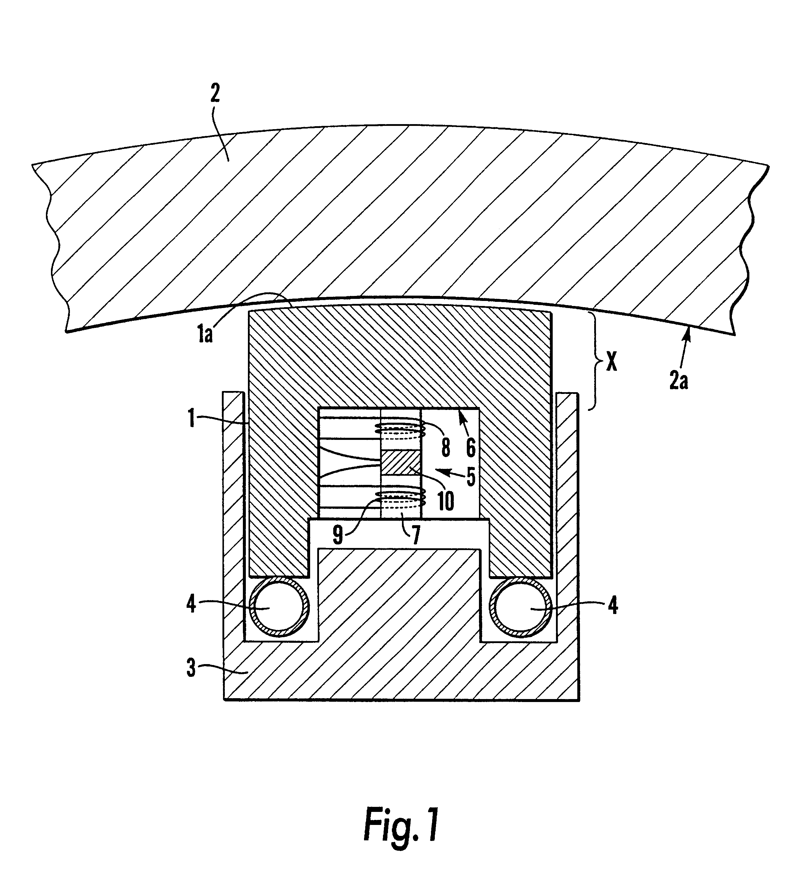
The object of the present invention is to solve the above mentioned problems, whereby there is presented a seal strip with indicator means arranged to continuously give a measure of a remaining wear allowance if the seal strip.

According to one aspect of the invention, said indicator means or at least a transmitter therefore, is mounted inside the seal strip, which seal strip at least in the main consists of a magnetically non-conducting material, preferably graphite, whereby the indicator means is arranged to continuously measure a distance between the indicator means, or the transmitter, and a surface against which the seal strip is arranged to seal.

According to another aspect of the invention, said indicator means include measuring based on electromagnetism. The methods of measurement may thereby be the per se known methods reluctance measurement, inductive measurement or eddy current measurement, reluctance measurement being the most preferred. Reluctance measurement is advantage...


PUM


Abstract

Seal strip for a hollow circular cylindrical screening device, which screening device is intended to be used in a paper or cardboard machine for the production of paper or cardboard, the seal strip having an indicator for indicating wear of the seal strip. The indicator is arranged to continuously give a measure of a remaining wear allowance and preferably also a wear rate, of the seal strip.

Description

The present invention relates to a seal strip for a hollow circular cylindrical screening device, which screening device is intended to be used in a paper or cardboard machine for the production of paper or cardboard, said seal strip exhibiting indicator means for indicating wear of the seal strip. The seal strip is e.g. intended to be used to seal between a vacuum box which is arranged inside the screening device, and the mantle of the screening device.STATE OF THE ART AND PROBLEMSIn the production of paper or cardboard, a continuous process for the dewatering of a paper pulp of cellulosic fibres is used, in order to form a sheet material. In connection with the dewatering there is thereby used so called suction rolls, i.e. hollow, rotating, circular cylindrical screening devices, in a paper or cardboard machine. Such suction rolls may be of different types, e.g. formation rolls which control the formation of the sheet, pick-up rolls which guide the pulp web, couch rolls or press s...

Claims


Application Information

Patent Timeline
IPC IPC(8): D21F3/10D21F3/02D21F2/00G01B7/00
CPCD21F3/10
Inventor PERSSON, ROLFERIKSSONANG.KERBLOM, BENGT
Owner JOCELL
Why Eureka
Try Eureka