Braided shield terminating potting backshell

a braided shield and backshell technology, applied in the direction of coupling base/case, coupling device connection, electrical apparatus, etc., can solve the problems of not having a small enough profile, rendering it difficult, if not impossible, to be connected to a mating receptacle, etc., and achieve the effect of simple profil

Inactive Publication Date: 2002-08-27
WESTINGHOUSE AIR BRAKE TECH CORP
View PDF6 Cites 22 Cited by
  • Summary
  • Abstract
  • Description
  • Claims
  • Application Information

AI Technical Summary

Benefits of technology

A further object of the present invention is to provide a new and improved terminating backshell to which a braided shield can be attached to provide 360.degree. of shielding around the wire, cable or wire harness connections within the backshell and having a simple profile small enough to permit such backshell's substantially unobstructed attachment to a mating receptacle of an electrical or electronic device.

Problems solved by technology

However, simple circular potting backshells to which a braided woven tubular shielding can be attached for providing 360.degree. of shielding are not available in a small enough profile to permit easy attachment of the backshell to a mating receptacle.
That is to say, commercially available terminating backshells are rather large in profile which renders them rather difficult, if not impossible, to be connected to a mating receptacle where there may be limited space adjacent the mating receptacle.

Method used


Image

  • Braided shield terminating potting backshell
  • Braided shield terminating potting backshell

Examples


Embodiment Construction

, particularly, when such description is taken in conjunction with the attached drawing figures as described below as well as with the appended claims.

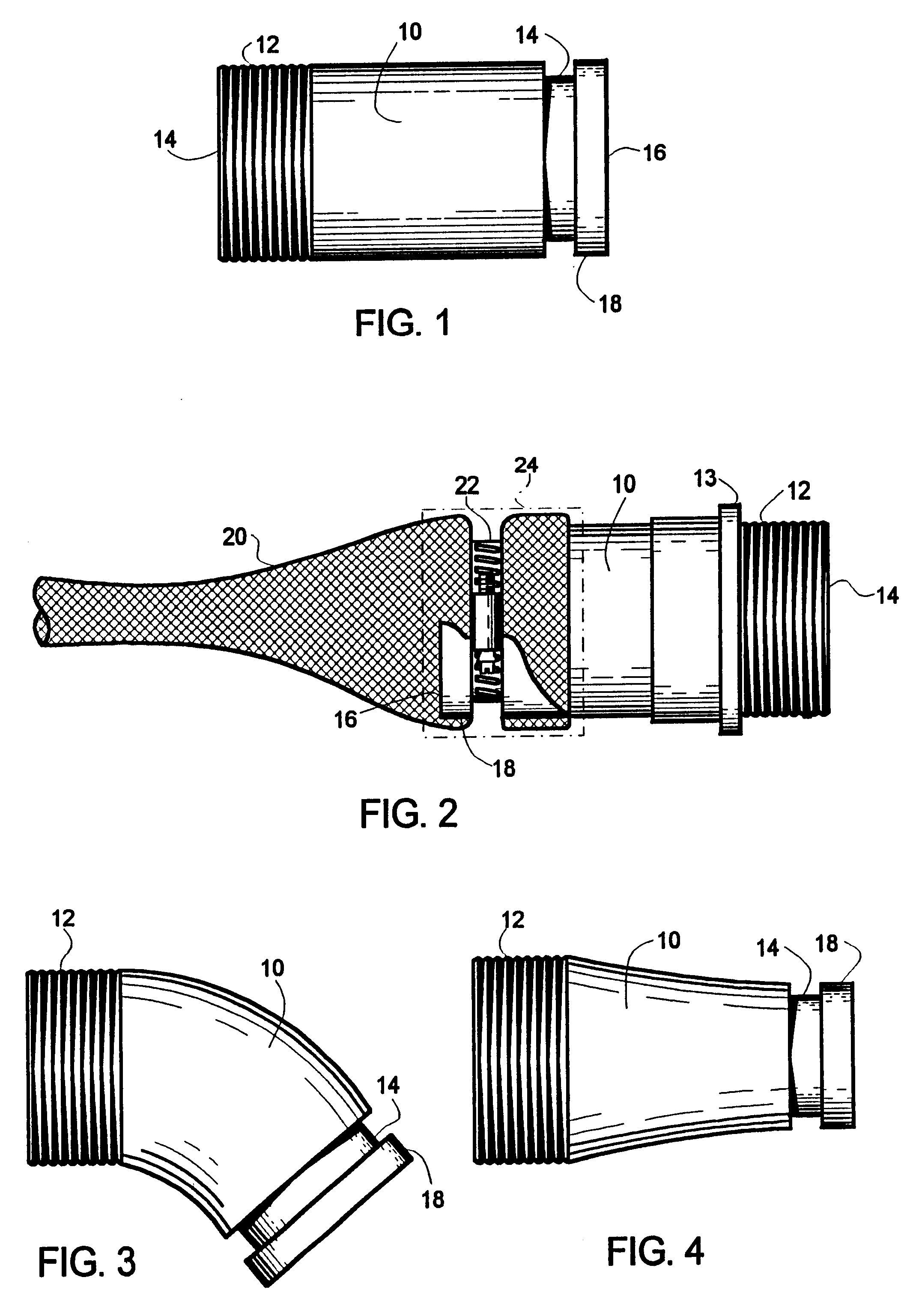
FIG. 1 is an elevational view of a presently preferred embodiment of the terminating potting backshell according to the invention.

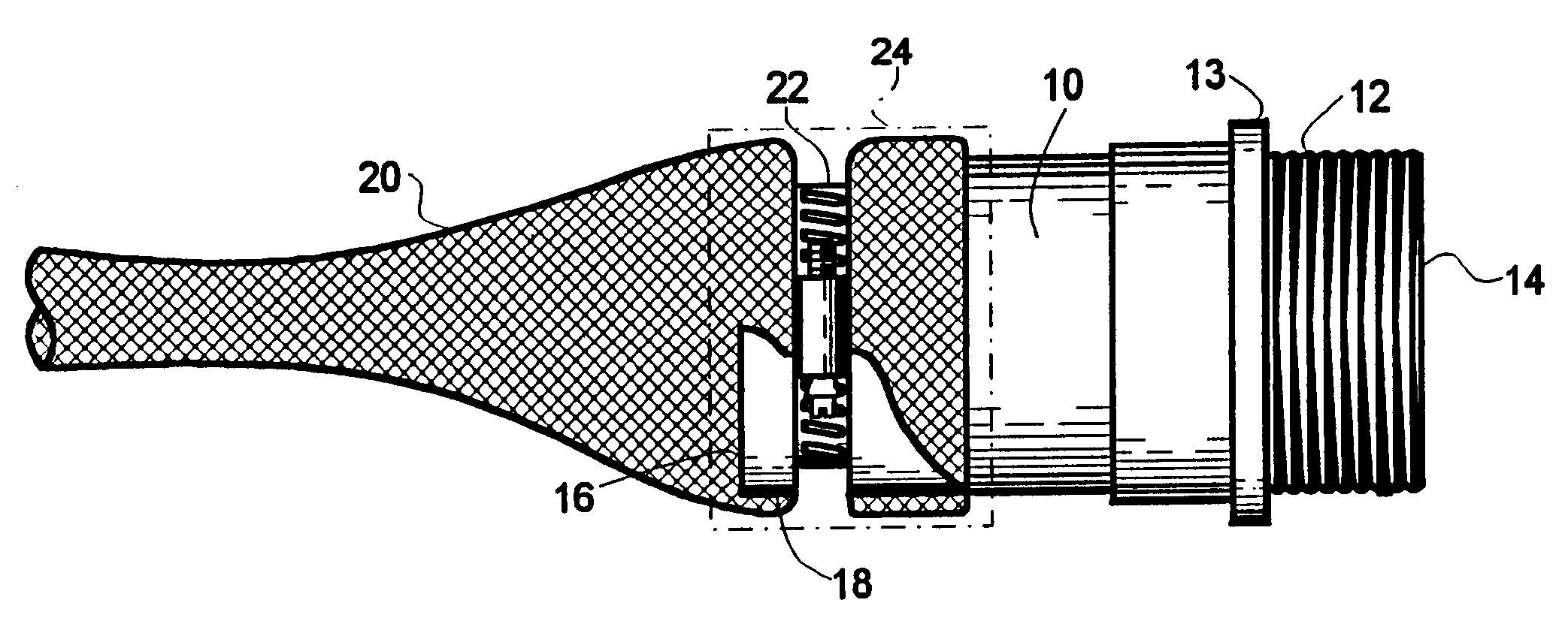
FIG. 2 is a side view of an alternative embodiment of a terminating potting backshell as it would appear in service when a braided shield is attached thereto.

FIGS. 3 and 4 illustrate other alternative embodiments of a terminating backshell which is indicative of the various shapes and forms in which the backshell can be provided.

DESCRIPTION OF THE PREFERRED EMBODIMENT OF THE INVENTION

Reference to FIGS. 1 and 2 will illustrate a presently preferred embodiment of the braided shield terminating potting backshell of this invention. Such backshell preferably comprises a generally tubular conductive body 10 having a threading 12 at a first end 14 thereof. Such threading 12 is provided for the purpose of attaching...


PUM


Abstract

A terminating potting backshell for connecting a wire or wire harness to a mating receptacle of an electrical / electronic device which is in the form of a generally tubular electrically conductive body and having threads encircling a first end for attaching the backshell to a mating receptacle on the electrical / electronic device and also having a groove spaced from a second end over which a conductive tubular braided shield can be disposed. The groove adapted to receive a clamp for holding the tubular braided shield onto the second end of the backshell.

Description

The present invention relates, in general, to a terminating backshell and, more particularly, this invention relates to a new and improved terminating potting backshell to which braided shielding can be attached to provide a full 360.degree. of wire shielding up to the backshell and further having a-relatively short profile which will facilitate such backshell's connection to a mating connector providing limited space adjacent thereto. In use, the backshell is intended to include a potting material to assure that any loose wire fibers from the braid shield do not contact any of the shielded wires, while the potting material also adds a degree of environmental protection and some strain relief to the soldered wire joints.Terminating backshells are generally well known in the electric and electronic arts as housings which cover and protect wire, cable and wire harness connections at a connector that is intended to be connected to a mating receptacle of an electric or electronic device...

Claims


Application Information

Patent Timeline
Patent Type & Authority Patents(United States)
IPC IPC(8): H01R9/03H01R13/658H01R13/58H01R13/6592
CPCH01R9/032H01R13/658H01R13/6592H01R13/5812H01R13/65912
Inventor JENETS, ROBERT J.
Owner WESTINGHOUSE AIR BRAKE TECH CORP
Why Eureka
Try Eureka