Pneumatic spring

a technology of pneumatic springs and springs, which is applied in the field of pneumatic springs, can solve the problems of comparatively high cost, high design cost of rolling bellows, and equivalent to a total failure of pneumatic springs, and achieve the effect of high reliability in operation and easy assembly

Inactive Publication Date: 2006-05-11
ZF FRIEDRICHSHAFEN AG
View PDF10 Cites 1 Cited by
  • Summary
  • Abstract
  • Description
  • Claims
  • Application Information

AI Technical Summary

Benefits of technology

[0008] An object of the present invention is to connect a rolling bellows to a connector part such as a cover

Problems solved by technology

This design of the rolling bellows is very expensive, because the reinforcing ring must be encased during the production of the rolling bellows.
This is equivalent to a total failu

Method used


Image

  • Pneumatic spring
  • Pneumatic spring
  • Pneumatic spring

Examples


Embodiment Construction

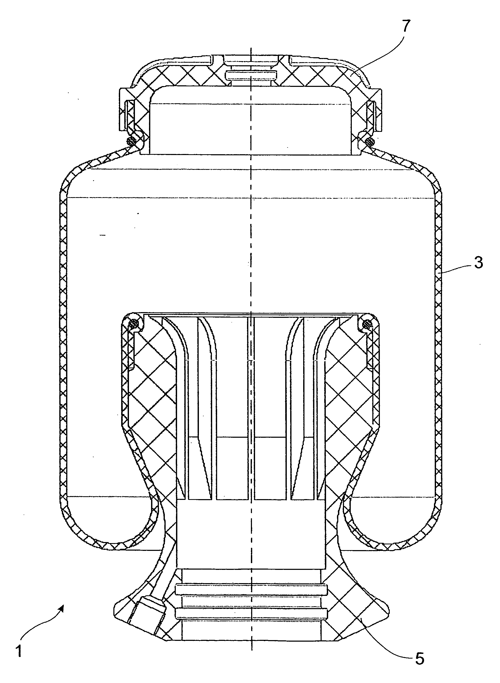
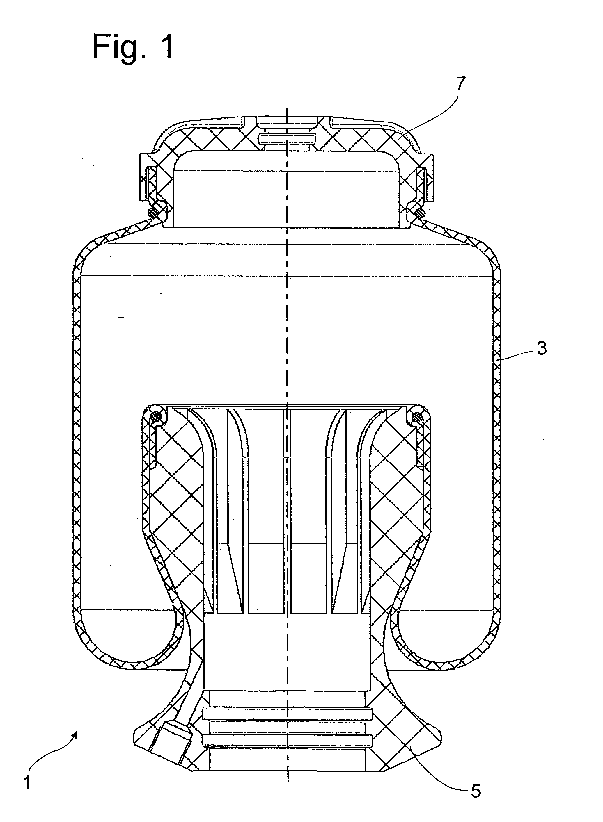
[0024]FIG. 1 shows a pneumatic spring 1, which has a rolling bellows 3. The bottom end of the rolling bellows 3 is connected to a roll-down tube 5, whereas its top end is connected to a cap 7, serving as a connector part. This structural assembly can be combined, for example, with a vibration damper, which carries the roll-down tube 5.

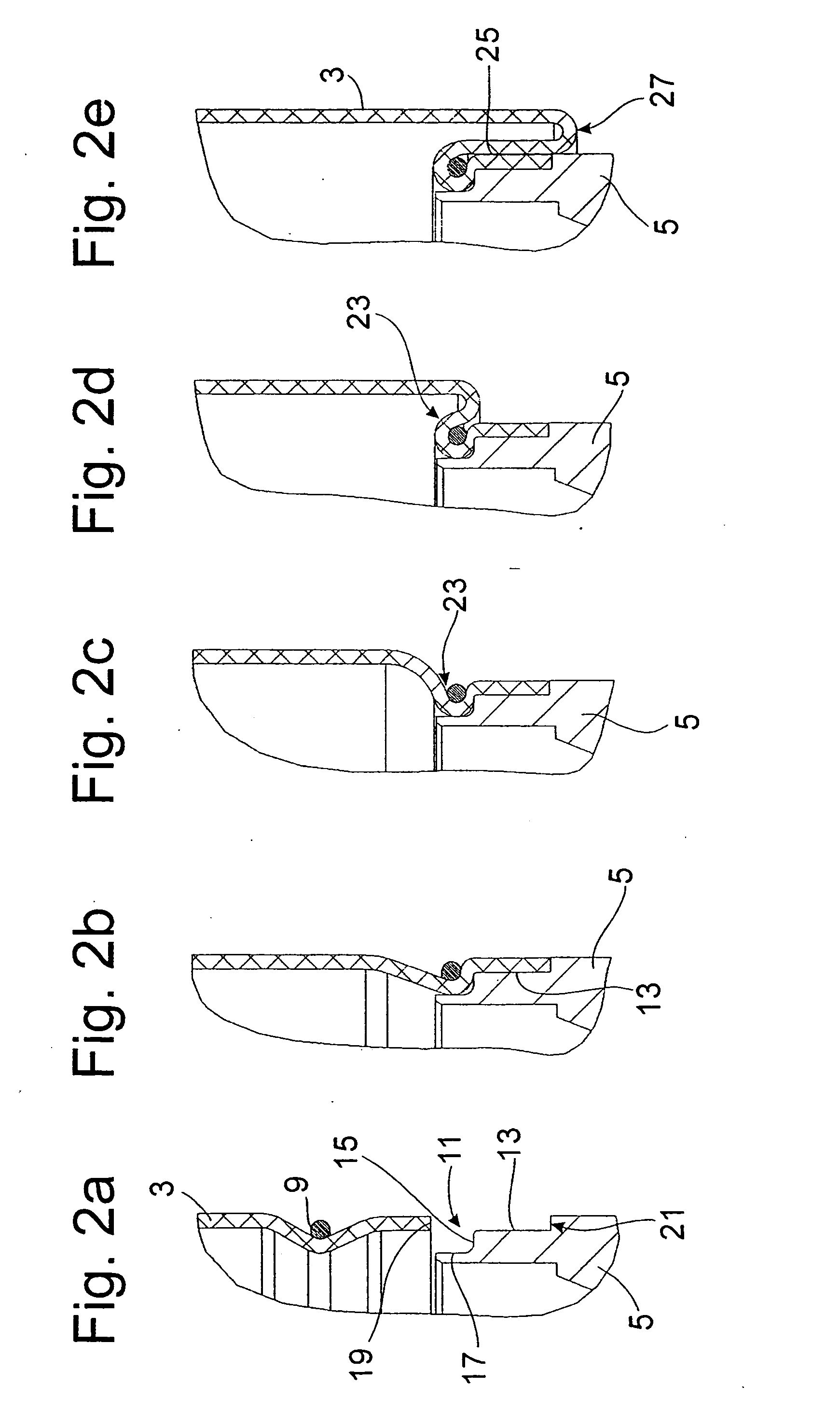
[0025]FIGS. 2a-2e illustrate the sequence of steps by which the rolling bellows 3 is mounted on the roll-down tube 5. The rolling bellows 3 is formed by a tubular body, which represents a semifinished product with a uniform cross section. This body is cut to the desired length from a strand. A clamping ring 9 is pushed onto the rolling bellows 3. The inside diameter of the clamping ring 9 is smaller than the outside diameter of the rolling bellows 3, as a result of which the rolling bellows 3 is squeezed inward to a slight degree. The clamping ring 9 is designed as an closed wire ring.

[0026] The roll-down tube has a profile with a shoulder 11, agains...


PUM


Abstract

Pneumatic spring comprises a rolling bellows, one end of which is attached to a connector part. The connector part has a profiling, which cooperates with a clamping ring to hold the rolling bellows in position. The profiling is in the form of a shoulder, against the axial surface of which the rolling bellows rests, where the rolling bellows is deformed axially by the clamping ring onto a radial clamping surface.

Description

BACKGROUND OF THE INVENTION [0001] 1. Field of the Invention [0002] The invention relates to a pneumatic spring. [0003] 2. Description of the Related Art [0004] An essential design feature of a pneumatic spring is the clamped connection between the rolling bellows and the cover or bottom piece. One possibility is to provide the rolling bellows with a reinforcing ring, which exerts radial tension against the cover or bottom piece. This design of the rolling bellows is very expensive, because the reinforcing ring must be encased during the production of the rolling bellows. [0005] In many cases, a hose-like rolling bellows is attached to the bottom piece or to the cover by means of clamping rings. When a pneumatic spring is subjected to compression, the rolling bellows expands and, under certain conditions, can thus be pulled away from the cover or bottom piece. This is equivalent to a total failure of the pneumatic spring. [0006] To avoid this situation, various types of clamping rin...

Claims


Application Information

Patent Timeline
IPC IPC(8): F16F9/04
CPCB60G2206/424F16F9/0463F16F9/05
Inventor MEMMEL, ALFREDMARKERT-HESS, CHRISTINENOWOTKA, THOMASPLANITZER, MATTHIASDRESCHER, HORST
Owner ZF FRIEDRICHSHAFEN AG
Why Eureka
Try Eureka