Filler neck

a technology of a flange and a flange is applied in the field of flange, which can solve the problems of undesirable evaporation into the ambient air

Inactive Publication Date: 2002-09-03
TESMA MOTOREN UND GETRIEBETECHN
View PDF2 Cites 15 Cited by
  • Summary
  • Abstract
  • Description
  • Claims
  • Application Information

AI Technical Summary

Benefits of technology

The object on which the invention is based is, therefore, in a filler neck of the type initially mentioned, to ensure in a simple way that the fuel droplets still subsequently running out no longer evaporate into the ambient air.
The set object is achieved, according to the invention, in that the actuating mechanism of the shutter cooperates with a damping device during the closing movement, in such a way that the shutter can be closed with a time delay.
This ensures in a simple way that droplets subsequently running out have sufficient time to run off in the direction of the fuel tank.
It is also particularly advantageous if the damping device is uncoupled from the actuatin mechanism when the shutter is closed. This ensures that any functioning of the spring-loaded shutter as a vacuum valve cannot be impaired and cannot be influenced by the damping device.
An embodiment of the invention is preferred, in which the shutter can be brought into its open position in a manner at least essentially uninfluenced by the damping device. The opening of the shutter during the introduction of the pump nozzle therefore does not require any additional forces to be overcome. This therefore also ensures that the damping device does not have to be co-actuated during the opening of the shutter, this being advantageous, for example, in the case of relatively low outside temperatures, where extra loads on the actuating mechanism could result in damage to the latter.
In this embodiment, the desired uncoupling of the damping device from the actuating mechanism of the shutter when the latter is in the closed position can follow in a very simple way, in that, during the closing movement of the shutter, the gearwheel comes out of engagement again with the rows of teeth on the rack.

Problems solved by technology

These fuel droplets remain on the closed shutter or in the region outside the latter and evaporate into the ambient air in an undesirable way.

Method used


Image

  • Filler neck
  • Filler neck

Examples


Embodiment Construction

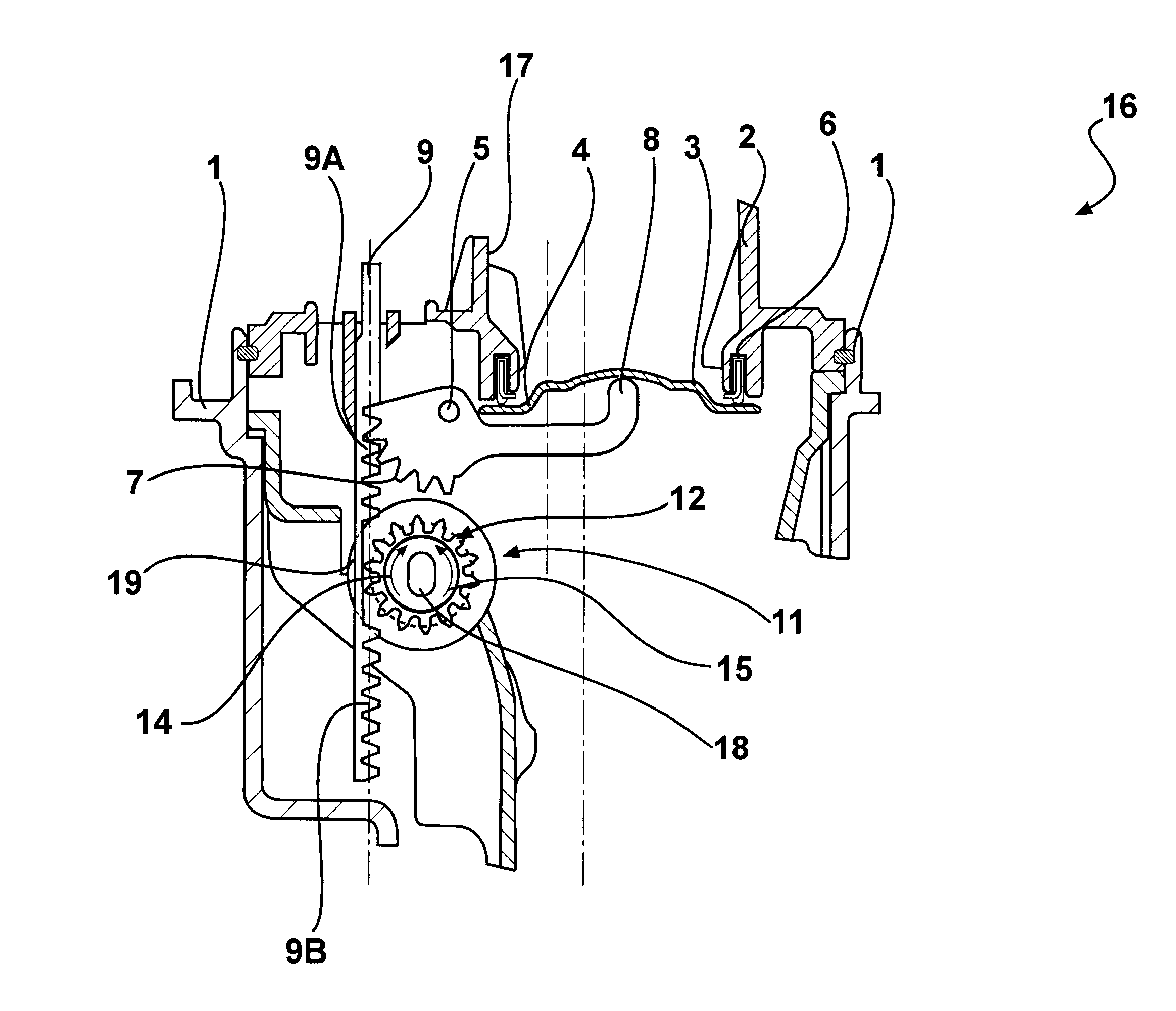
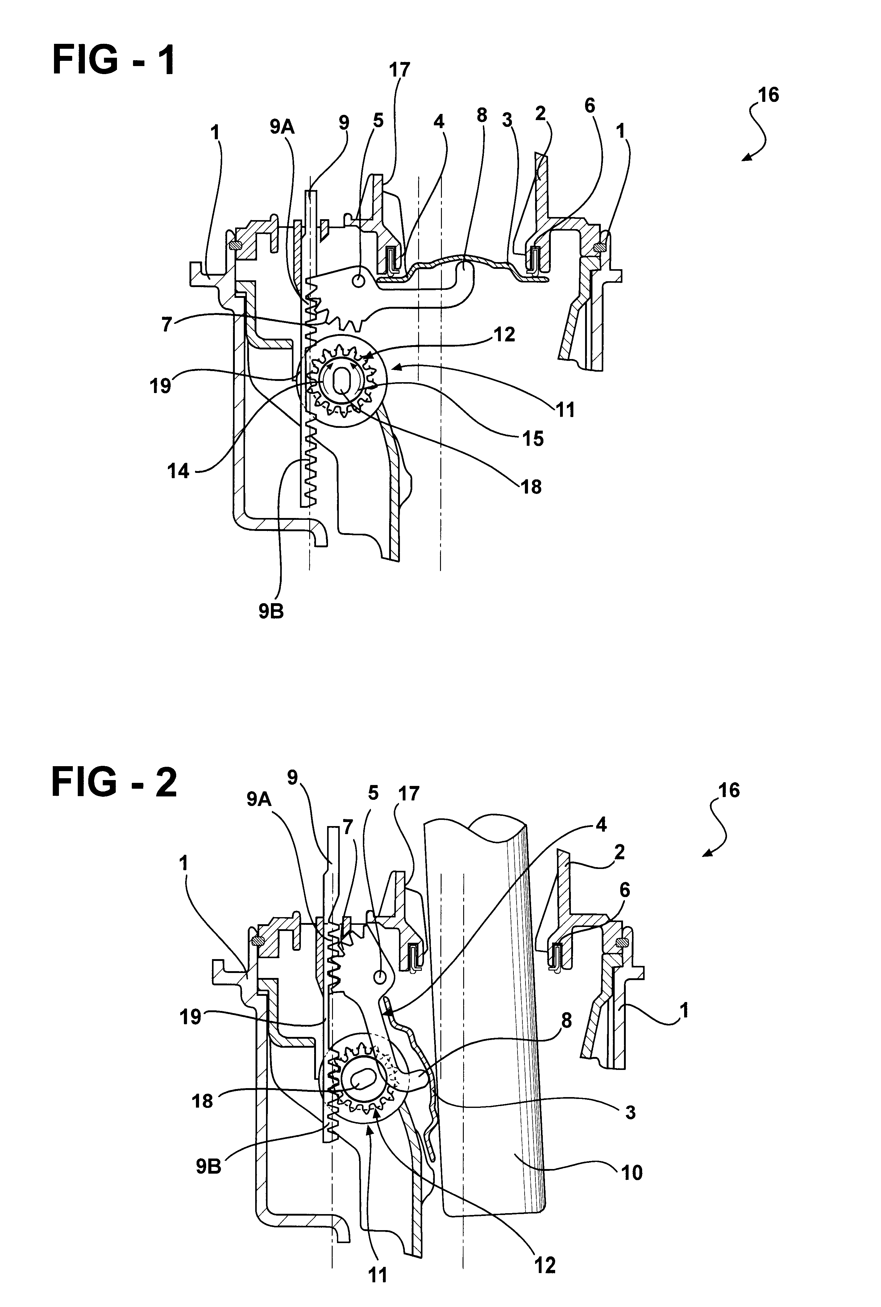
The Figures of the drawings illustrate only those parts of the filler neck which are important for the functioning and understanding of the present invention. It is pointed out that the other components which are not illustrated may be designed, in particular, according to the embodiment of a filler neck illustrated in FIGS. 1-6 of WO 99 / 03697. The following description also refers at some points to WO 99 / 03697, which is incorporated by reference herein in its entirety.

Referring to FIGS. 1 and 2, a filler neck for a fuel tank of a motor vehicle is generally illustrated at 16 including an outer housing 1, shown only partially here, on which an outer flap can be mounted so as to cover the filler neck 16 from outside ambient air. The configuration and arrangement of the outer flap may be similar to those according to FIGS. 3 and 4 of WO 99 / 03697. When the fuel tank of the vehicle is being filled, this outer flap is opened, and, after filling up, is closed again.

The actual cap of the fi...


PUM

PropertyMeasurementUnit
timeaaaaaaaaaa
forcesaaaaaaaaaa
temperaturesaaaaaaaaaa

Abstract

A filler neck for the fuel tank of a motor vehicle with a shutter which is mounted inside the filler neck and which can be actuated by the pump nozzle into an open position for filling the fuel tank and into a closed position via an actuating mechanism. The actuating mechanism of the shutter cooperates with a damping device during the closing movement in such a way that the shutter can be closed with a time delay.

Description

The invention relates to a filler neck for a fuel tank of a motor vehicle. More particularly, the invention relates to a filler neck with a shutter which is mounted inside the filler neck and can be brought by a pump nozzle into an open position for filling the fuel tank and into a closed position via an actuating mechanism for closing the filler neck.BACKGROUND OF INVENTIONA filler neck for a fuel tank of a motor vehicle is known, for example, from WO 99 / 03697. In this filler neck, an internally mounted shutter is provided, which replaces the generally conventional tank caps capable of being either screwed on or attached via a bayonet fastening from outside to the filler neck of the fuel tank. The shutter, when in a closed position, ensures a gas-tight and liquid-tight seal between the fuel tank on one side and the ambient air on the other side. An actuating mechanism operates in such a way that the shutter is immediately closed as soon as a fuel pump nozzle has been drawn out of t...

Claims


Application Information

Patent Timeline
Patent Type & Authority Patents(United States)
IPC IPC(8): B60K15/04E05B65/12E05B17/00E05B77/42E05B83/34
CPCB60K15/04B60K15/0406E05B83/34E05B77/42
Inventor PALVOELGYI, SANDORPOZGAINER, GUNTHERLACKNER, GERALDMAIER, BERNHARD
Owner TESMA MOTOREN UND GETRIEBETECHN
Why Eureka
Try Eureka