
In-plane switching scheme liquid crystal display unit

Inactive Publication Date: 2002-09-17
NEC LCD TECH CORP
View PDF19 Cites 57 Cited by
  • Summary
  • Abstract
  • Description
  • Claims
  • Application Information

AI Technical Summary

Problems solved by technology

However, the conventional IPS-LCD has a disadvantage in that the observed color changes toward blue or red color depending on the view angle.
In the LC cell having the bends in electrodes, the bends cause reduction of ratio of the effective pixel area to the total pixel area of each cell and also may cause defects in each pixel such as an open-circuit failure.

Method used


Image

  • In-plane switching scheme liquid crystal display unit
  • In-plane switching scheme liquid crystal display unit
  • In-plane switching scheme liquid crystal display unit

Examples


Embodiment Construction

Now, the present invention is more specifically described with reference to accompanying drawings.

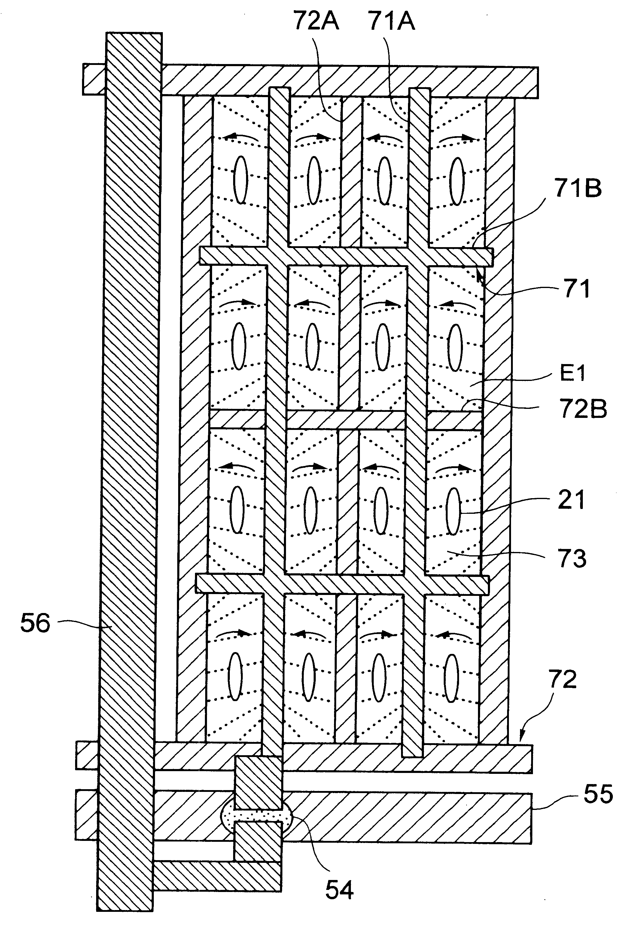
Referring to FIG. 6, there is shown a LC cell of an IPS-LCD unit according to a first embodiment of the present invention, with a front substrate being omitted. The IPS-LCD unit includes the front (first) substrate disposed at the near side of the drawing, a LC layer including LC molecules having a uniform initial alignment, and a rear (second) substrate disposed at the far side of the drawing, which are consecutively disposed in the direction opposite to the travelling direction of the back-light. The rear substrate includes a plurality of gate bus lines 55 extending in the horizontal direction, a plurality of drain bus lines 56 extending in the vertical direction. A plurality of pixel areas or LC cells are disposed in a matrix, each pixel area being substantially of a rectangular shape defined by adjacent gate bus lines 55 and adjacent drain bus lines 56. An active element 54 implemen...


PUM


Abstract

An in-plane switching scheme LCD (IPS-LCD) unit includes front and rear substrates, a LC layer sandwiched therebetween and having a uniform initial orientation alignment. The rear substrate has in each pixel area a plurality of zones formed by stripes of a pixel electrode and stripes of a common electrode. The electric fields generated by the pixel electrode and the common electrode extend alternately in opposite directions to form a checkered pattern, thereby suppressing color change due to the view angle for the LCD.

Description

(a) Field of the InventionThe present invention relates to an in-plane switching scheme liquid crystal display (LCD) unit and, more particularly, to an in-plane switching scheme LCD unit having driving electric field parallel to substrates and achieving a wide view angle while suppressing a color change.(b) Description of the Related ArtLCD units have advantages of smaller thickness, lower weight and lower power dissipation. Among other LCD units, an active matrix LCD unit wherein each of pixels arranged in a matrix is driven by an active element, such as a thin film transistor (TFT), is expected for use as a high-performance flat panel display unit.A conventional active matrix LCD unit (AM-LCD) generally includes a twisted-nematic liquid crystal (TN-LC) layer and takes advantage of the electric-optical effect thereof by sandwiching the LC layer between a pair of substrates and applying the LC layer with an electric field substantially perpendicular to the surfaces of the substrates...

Claims


Application Information

Patent Timeline
IPC IPC(8): G02F1/1343G02F1/13G02F1/136G02F1/1368G02F1/1337
CPCG02F1/134363
Inventor SUZUKI, TERUAKINISHIDA, SHIN-ICHISUZUKI, MASAYOSHI
Owner NEC LCD TECH CORP
Features
  • Generate Ideas
  • Intellectual Property
  • Life Sciences
  • Materials
  • Tech Scout
  • Unparalleled Data Quality
  • Higher Quality Content
  • 60% Fewer Hallucinations
Learn More