Carbon dioxide concentration sensor

a technology of concentration sensor and carbon dioxide, which is applied in the direction of liquid/fluent solid measurement, instruments, machines/engines, etc., can solve the problem of practically difficult to achieve accurate calibration

Inactive Publication Date: 2002-09-24
RIKEN KEIKI KK
View PDF13 Cites 23 Cited by
  • Summary
  • Abstract
  • Description
  • Claims
  • Application Information

AI Technical Summary

Problems solved by technology

In modern offices and other similar extremely airtight buildings, however, accurate calibration is practically difficult to achieve because it takes a very long time for the carbon dioxide concentration to reach the minimum value.

Method used


Image

  • Carbon dioxide concentration sensor
  • Carbon dioxide concentration sensor
  • Carbon dioxide concentration sensor

Examples


Embodiment Construction

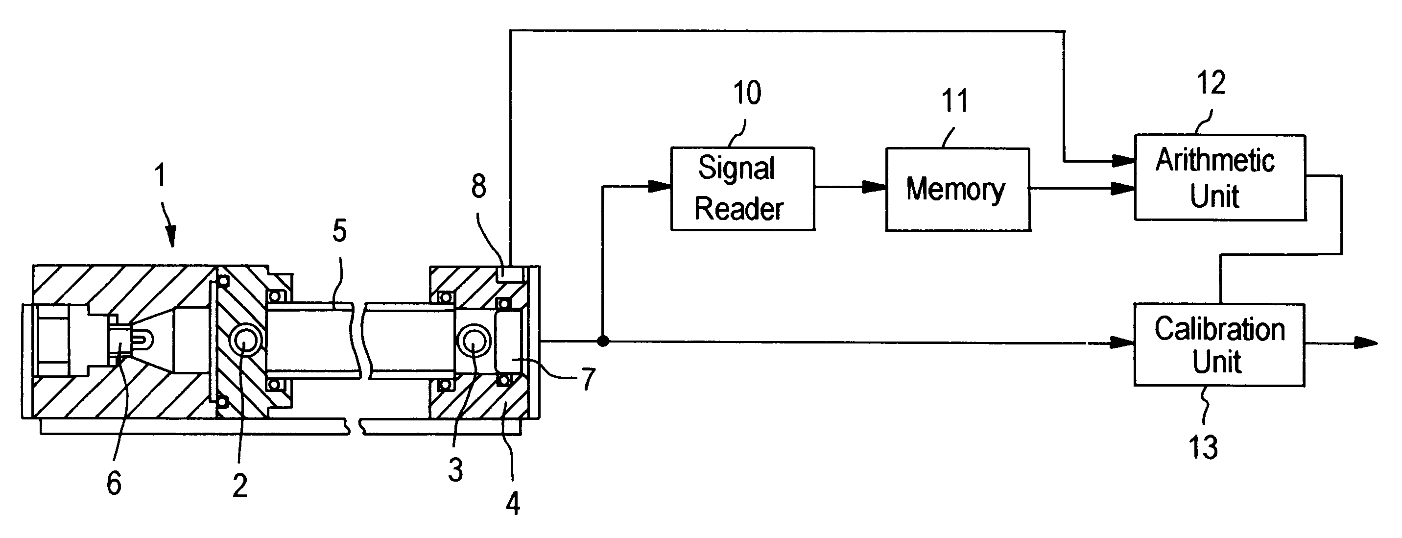
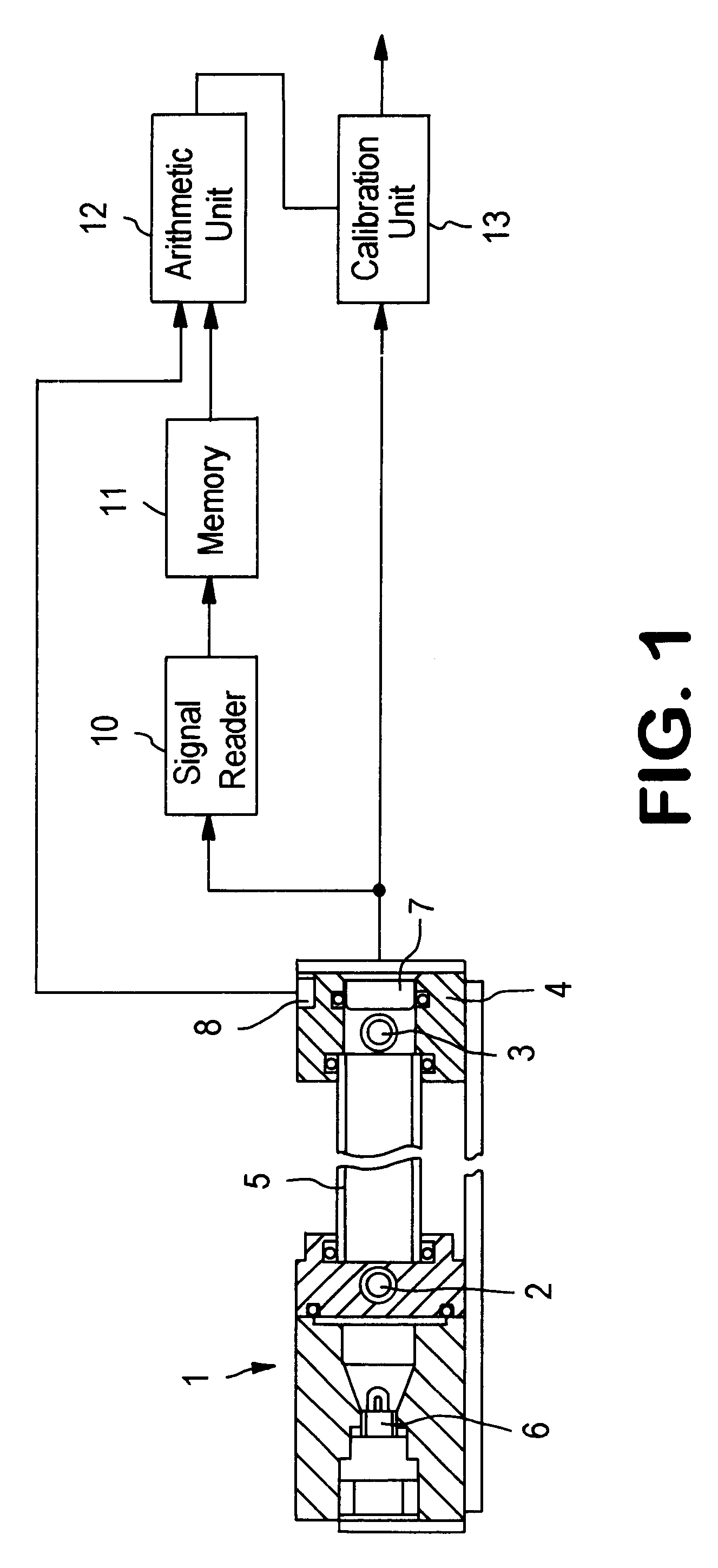
FIG. 1 shows a carbon dioxide concentration sensor according to this invention, which comprises a carbon dioxide sensing unit. A non-dispersive infrared sensor 1 serving as the carbon dioxide sensing unit in this embodiment comprises a chamber 5 fastened to a base 4 having a gas inlet 2 and a gas outlet 3 at both ends thereof, an infrared-ray emitter 6, such as an incandescent lamp used here, on one side of the chamber, an infrared-ray sensor 7, such as a pyroelectric infrared ray sensor used here, and, if required, a temperature sensor 8.

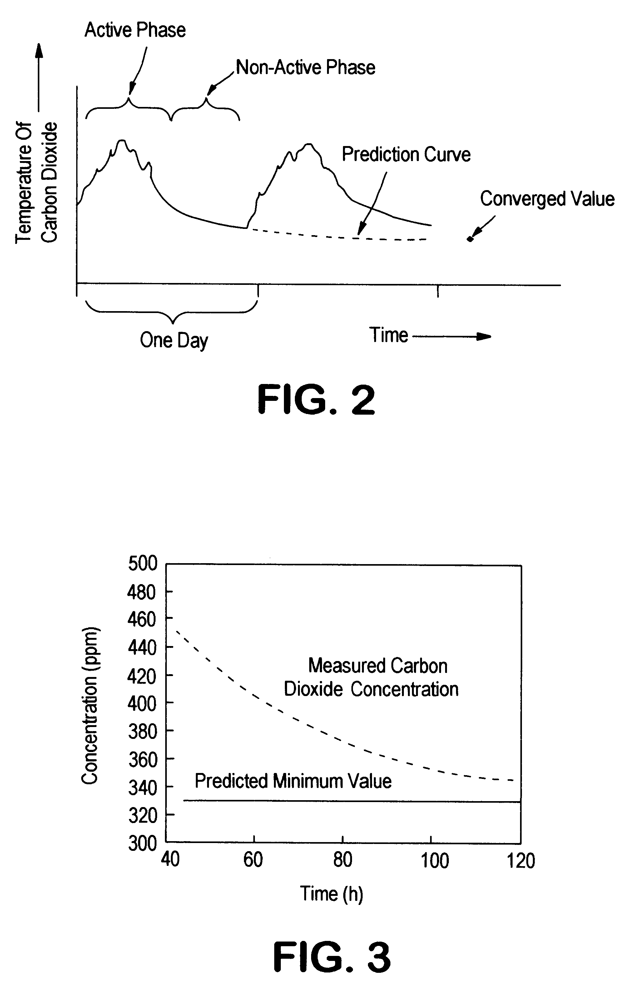
A signal fetching unit 10 fetches signals from the infrared-ray sensor 7 into a memory 11 at given intervals, such as at intervals of 10 minutes. An arithmetic unit 12 is configured to arithmetically predict the minimum value of carbon dioxide in the environment in which no person is present based on the signals stored in the memory when the carbon dioxide concentration in the environment shows a tendency to drop at preset times, or under predeterm...


PUM

PropertyMeasurementUnit
concentrationaaaaaaaaaa
temperatureaaaaaaaaaa
concentrationsaaaaaaaaaa

Abstract

A carbon dioxide sensor has an arithmetic unit 12 that predicts the minimum value of carbon dioxide concentration that is regulated by the diffusion of the atmosphere by judging that a signal from a carbon dioxide concentration sensing unit 1 indicates a declining tendency and a calibration unit 13 that updates the sensitivity correction factor based on the predicted minimum value. This permits quick calibration by eliminating the need to wait until the carbon dioxide concentration in any given environment reaches the minimum value.

Description

This invention relates to carbon dioxide concentration sensors that determine the concentration of carbon dioxide in a given environment while carrying out calibration based on the carbon dioxide concentration in the reference atmosphere.DESCRIPTION OF THE PRIOR ARTOutputs from carbon dioxide sensors employing solid electrolytes or infrared rays vary with time. Therefore, such sensors correct their sensitivity by using calibration data prepared by statistically processing the chronologically measured and stored carbon dioxide concentrations in the reference air, as described in Japanese Provisional Patent Publication No. 249073 of 1993.This type of sensors permit correction of changes in the carbon dioxide sensing means with age if the concentration of carbon dioxide in the environment has lowered to the level of carbon dioxide in the reference air. In modern offices and other similar extremely airtight buildings, however, accurate calibration is practically difficult to achieve bec...

Claims


Application Information

Patent Timeline
Patent Type & Authority Patents(United States)
IPC IPC(8): G01N33/00G01N21/61
CPCG01N33/0006G01N33/004Y02A50/20
Inventor KOGURE, SHINSUKEYONEMURA, SHINICHI
Owner RIKEN KEIKI KK
Why Eureka
Try Eureka