Printed circuit board connector

a technology of printed circuit board and connector, which is applied in the direction of incorrect coupling prevention, coupling device connection, coupling device details, etc., can solve the problems of large number of parts, high assembling cost, and failure to establish the connection between male and female connectors

Inactive Publication Date: 2002-10-01
KK TOKAI RIKA DENKI SEISAKUSHO
View PDF2 Cites 21 Cited by
  • Summary
  • Abstract
  • Description
  • Claims
  • Application Information

AI Technical Summary

Problems solved by technology

However, in the related case of connecting the printed circuit boards by using such a cable, there are problems in that the number of man-hours required to assemble such parts into an apparatus is large, that moreover, the number of the parts is large, and that consequently, the assembling cost thereof is high.
However, this method causes problems that the positional displacement between the male and female connectors occurs owing to variation in assembling accuracy (that is, an assembling tolerance) in assembling the units (namely, the printed circuit boards), and that thus, the connection between the male and female connectors is not successfully established.
Thus, there is a fear that the terminal is broken or bent by the shifting movement of the upper housing.

Method used


Image

  • Printed circuit board connector
  • Printed circuit board connector
  • Printed circuit board connector

Examples


Embodiment Construction

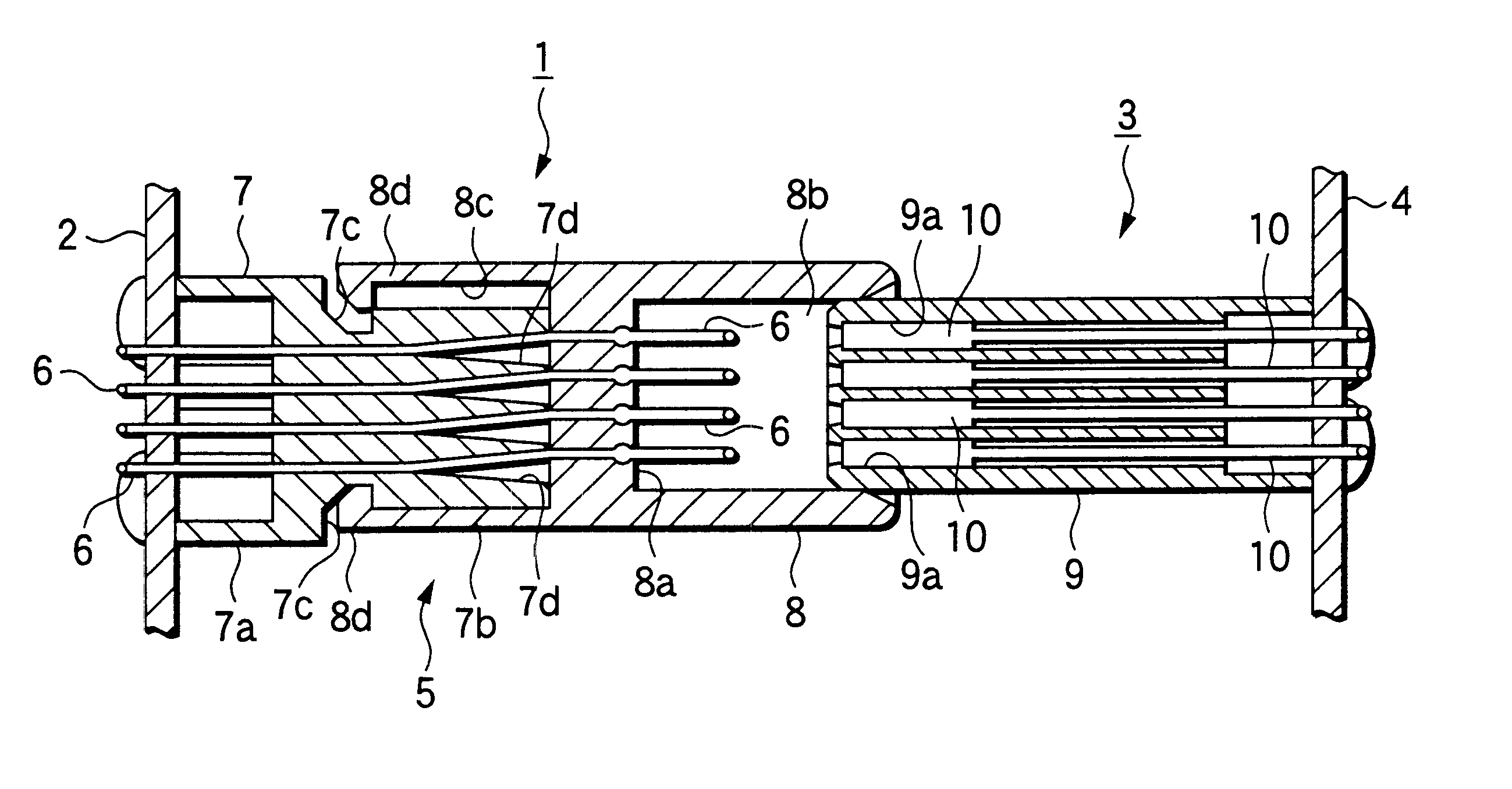
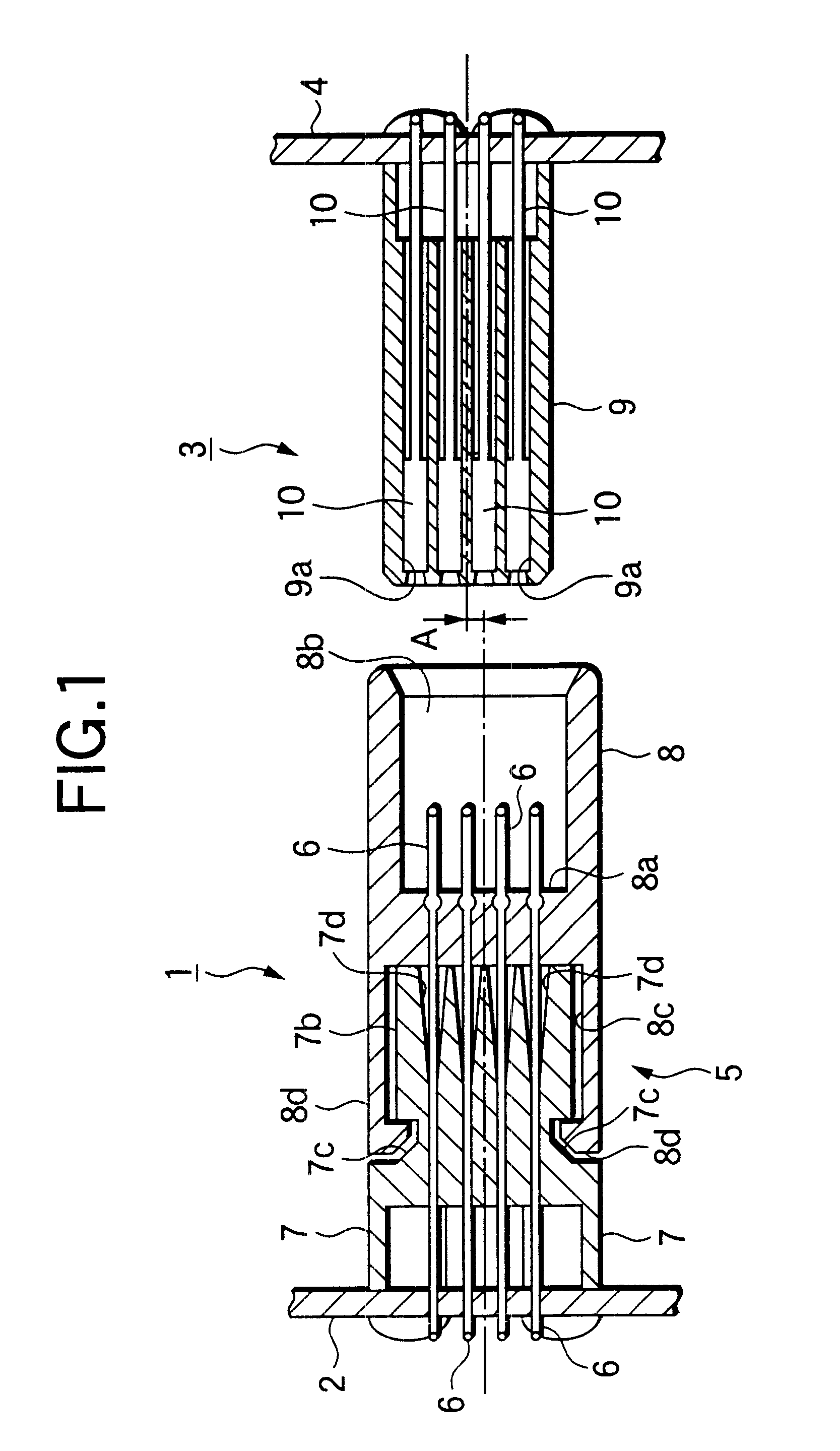
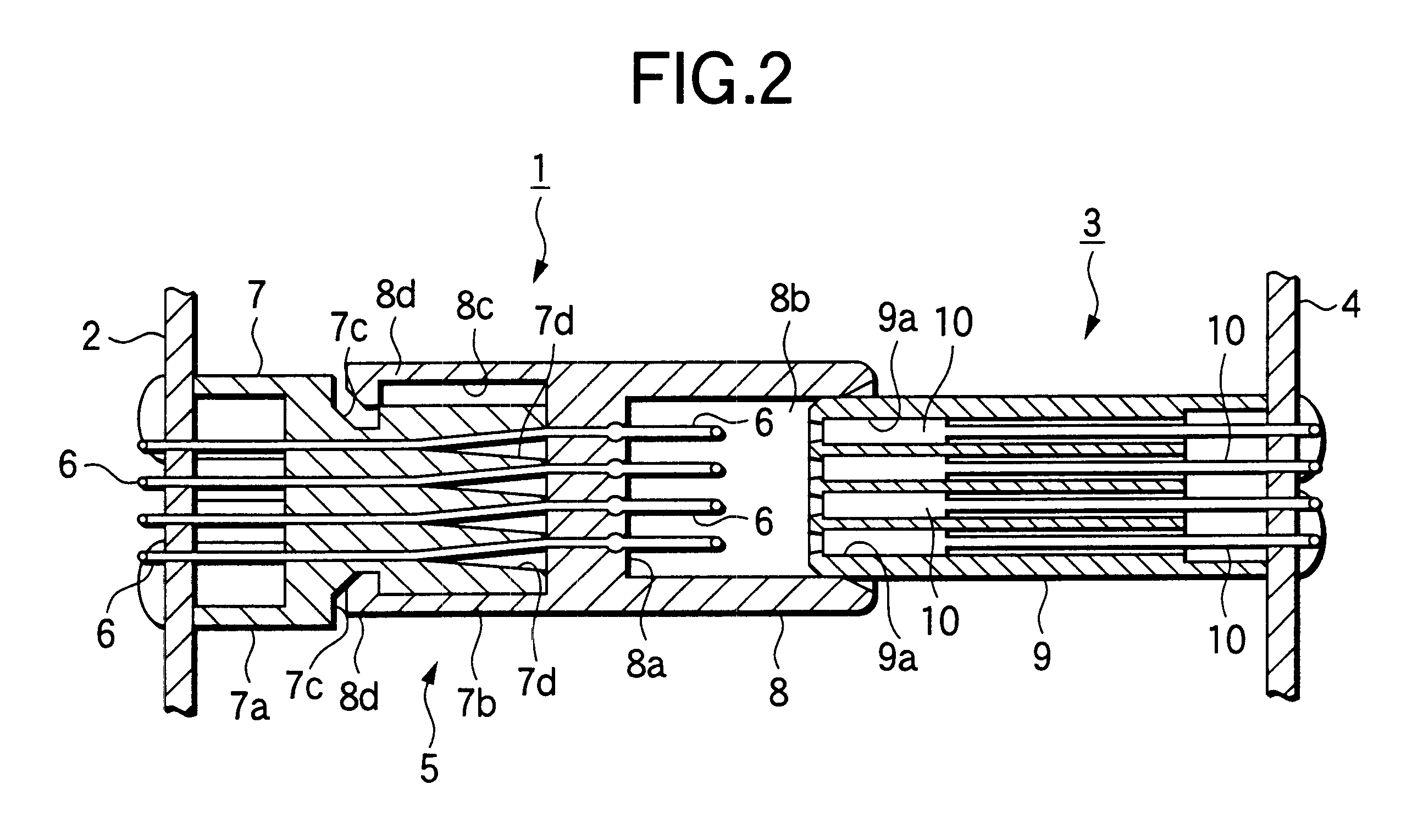
Hereinafter, an embodiment of the invention is described with reference to the accompanying drawings. FIGS. 1 and 2 are longitudinally sectional views illustrating a manner, in which a printed circuit board connector 1 according to the invention is mounted on a printed circuit board 2, and a manner, in which a mating connector 3 to be paired with the connector 1 is mounted on another printed circuit board 4. In this embodiment, the connector 1 is constituted as a male connector. Further, the mating connector 3 is constituted as a female connector.

The connector 1 according to this embodiment is configured by supporting a plurality of male terminals (in the case shown in the drawings, four male terminals) 6 in a connector housing 5 made of an insulating material (that is, a synthetic resin) At that time, the connector housing 5 is constituted by connecting two members into which the housing 5 is divided, that is, a lower housing 7 provided at the base side, namely, at the side to be m...


PUM


Abstract

A connector housing (1) of a connector (1) is constituted by a lower housing (7), which is mounted on a printed circuit board (2), and an upper housing (8) connected to the lower housing (7) in such a manner as to be able to perform shifting movement with respect the housing (7). Further, terminals (6) are provided in such a way as to penetrate through a partitioning wall portion (8a) of the upper housing (8) and through a connecting block portion (7b) of the lower housing (7). At that time, tapered holes (7d) are provided in the connecting block portion (7b). The terminals (6) are maintained in a state in which a bending deformation thereof caused by the shifting movement of the upper housing (8) is allowed. Consequently, when the connector (1) is connected to the mating connector (3), the connectors (1, 3) can be connected to each other by performing the shifting movement of the upper housing (8) thereby to concurrently absorb the positional displacement therebetween. Moreover, occurrences of problems, such as breakage and bend of the terminals (6) at that time, are prevented.

Description

1. Technical Field of the InventionThe present invention relates to a printed circuit board connector, which is mounted on a printed circuit board and connected to a mating connector.2. Related ArtFor example, in a lever combination switch for use in a vehicle, two units (that is, printed circuit boards) are electrically connected to each other by using connectors. Hitherto, this has been performed by mounting male connectors on both the printed circuit boards, respectively, and then connecting the male connectors to each other by using a cable having both ends to which female connectors are respectively attached. However, in the related case of connecting the printed circuit boards by using such a cable, there are problems in that the number of man-hours required to assemble such parts into an apparatus is large, that moreover, the number of the parts is large, and that consequently, the assembling cost thereof is high.Thus, there has been devised a method of mounting a male connec...

Claims


Application Information

Patent Timeline
Patent Type & Authority Patents(United States)
IPC IPC(8): H01R12/16H01R12/00H01R13/631H01R12/70H01R24/00H01R107/00
CPCH01R12/7082H01R13/6315
Inventor HATTORI, TETSUYAKATO, YOSHIAKIITO, KEIICHISHIRAKI, KAZUYUKIWAKUI, MASANORI
Owner KK TOKAI RIKA DENKI SEISAKUSHO
Why Eureka
Try Eureka