Vehicle seat

a seat and vehicle technology, applied in the field of vehicle seats, can solve the problem of poorly defined flat position of said seat, and achieve the effect of restricting the displacement of the top par

Inactive Publication Date: 2002-10-15
FAURECIA
View PDF13 Cites 76 Cited by
  • Summary
  • Abstract
  • Description
  • Claims
  • Application Information

AI Technical Summary

Benefits of technology

and the top part of the backrest is designed to co-operate with the seat part by means of a stop when said top part is in the flat position, in order to restrict displacement of the top part of the backrest when folded forward.
As a result of these feature

Problems solved by technology

As a result, said flat position is poorly defined and in certain instances the top part of the backr

Method used


Image

  • Vehicle seat
  • Vehicle seat
  • Vehicle seat

Examples


Embodiment Construction

The same reference numbers are used to denote the same or similar elements in the different drawings.

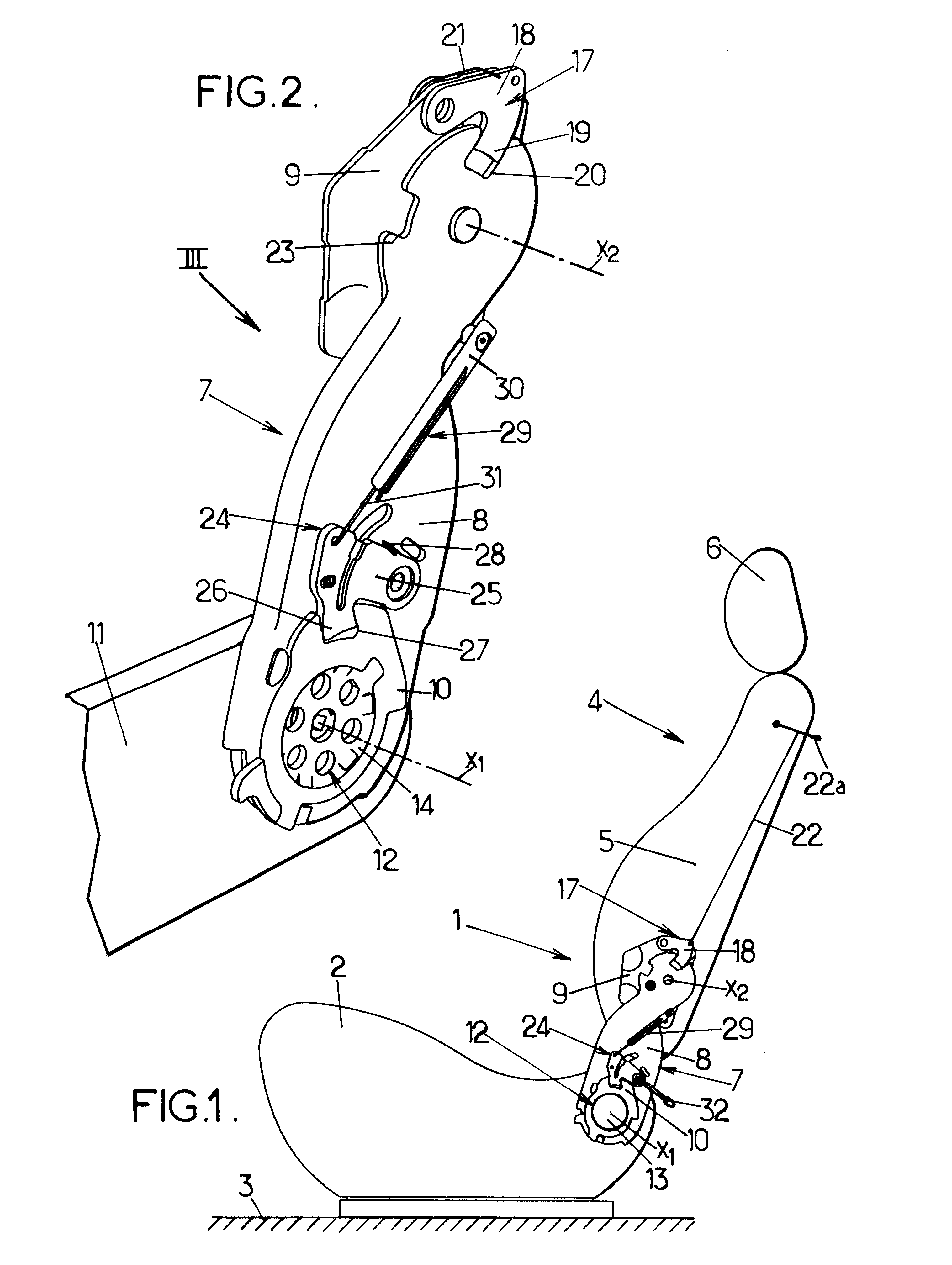
FIG. 1 illustrates a motor vehicle seat 1, in this case a front seat (although the invention could, of course, also be applied to a rear seat), this seat comprising a seat part 2 mounted on the floor 3 of the vehicle and a backrest 4 which is pivotally mounted on the seat part about a first transverse, horizontal axis X1.

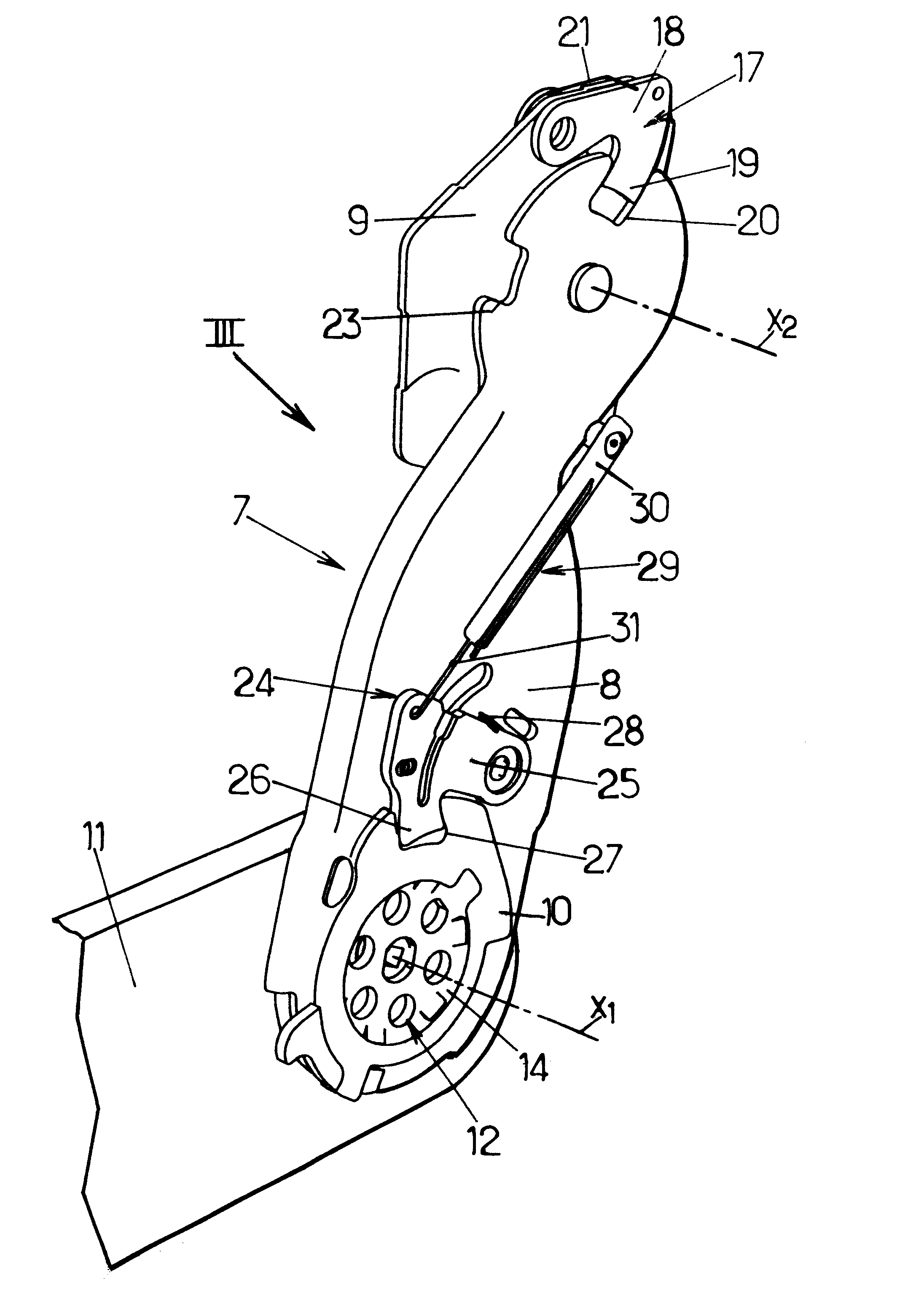
The backrest 4 comprises a top part 5, which, in the example illustrated here, consists of a headrest 6, and which is pivotally mounted on a bottom part 7 of the backrest about a second transverse, horizontal axis X2 parallel with the first axis X1.

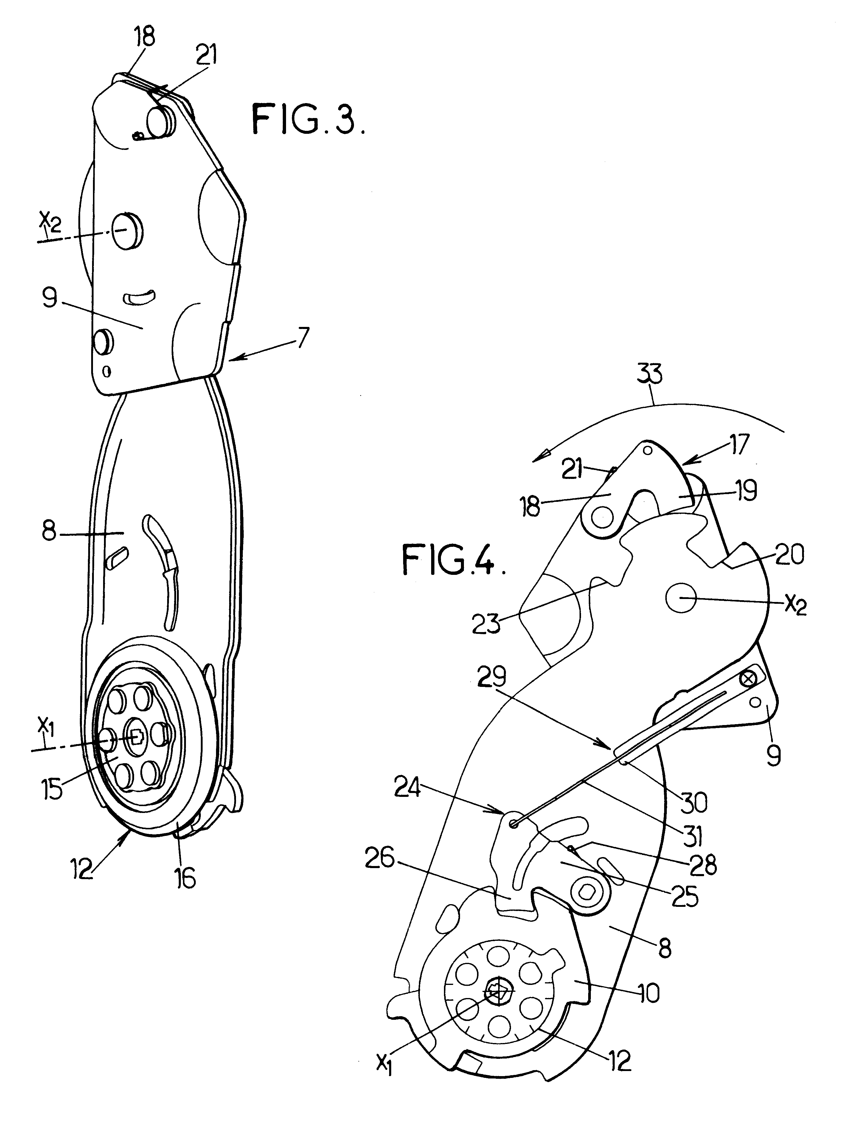
As may be seen from FIGS. 1 to 3, the bottom part 7 of the backrest comprises:

a support frame 8, which, in the example illustrated here, comprises two sheet-metal side plates disposed on either side of the seat, this support frame being pivotally linked, about the second axis X2, to metal side plates 9 belonging to the fra...


PUM


Abstract

Vehicle seat comprising a backrest and a seat part, a lower part of the backrest having a support frame and an intermediate frame which are pivotally mounted about a first axis on the seat part. The intermediate frame is linked to the seat part by an inclination-adjusting mechanism and to the support frame by a locking device. The support frame bears a top part of the backrest, which can be folded down into a flat position and which is linked to a mechanical coupling device designed to release the support frame when the top part of the backrest is in its flat position.

Description

The present invention relates to vehicle seats.More specifically, the invention relates to a vehicle seat comprising a backrest and a seat part, the backrest in turn comprising:a bottom part comprising a support frame which is pivotally mounted about a first transverse, horizontal axis of rotation by means of a pivot mechanism designed to allow a user to adjust an angular position of the backrest relative to the seat part,and a top part pivotally mounted on the support frame about a second transverse, horizontal pivot axis parallel with the first axis, the top part of the backrest being linked to the support frame by means of a first locking mechanism designed to link the top part of the backrest to the support frame at least in an angular position of normal usage, the first locking mechanism being controlled by a first operating member to release the top part of the backrest, allowing it to pivot about the second axis, at least so as to fold it forward from the normal position of u...

Claims


Application Information

Patent Timeline
IPC IPC(8): B60N2/02B60N2/20
CPCB60N2/206B60N2205/30
Inventor CASTAGNA, STEPHANE
Owner FAURECIA
Why Eureka
Try Eureka