Internal multi-band antennas for mobile communications

a multi-band antenna and mobile communication technology, applied in the direction of resonant antennas, substantially flat resonant elements, antenna earthings, etc., can solve the problems of inconvenient user experience, insufficient bandwidth of conventional internal antenna designs, and prior attempts to achieve the effect of success

Inactive Publication Date: 2002-10-15
MALIKIE INNOVATIONS LTD
View PDF10 Cites 99 Cited by
  • Summary
  • Abstract
  • Description
  • Claims
  • Application Information

AI Technical Summary

Problems solved by technology

Additionally, external and retractable antennas are exposed outside the telephone housing, which is inconvenient for the user.
Internal antennas have been proposed to replace external and retractable antennas, but conventional internal antenna designs have do not provide adequate bandwidth, especially for dual mode applications.
It is desirable in some applications to provide thin antennas capable of operating in multiple bands having the advantages associated with patch antennas, but prior attempts have been unsuccessful.
Additionally, known internal patch antennas tend to have a narrow bandwidth, unless a thick dielectric substrate is employed, but the resulting thickness limits use of the antennas in many applications, particularly in handheld mobile communication devices with severe space and weight constraints.
These large dimensions however are unacceptable for most modern cellular telephone devices, which often require that the antenna be less than approximately 4 cm in length.
Known PIFA antennas have limitations and generally are not suitable for multi-mode and space limited applications.

Method used


Image

  • Internal multi-band antennas for mobile communications
  • Internal multi-band antennas for mobile communications
  • Internal multi-band antennas for mobile communications

Examples


Embodiment Construction

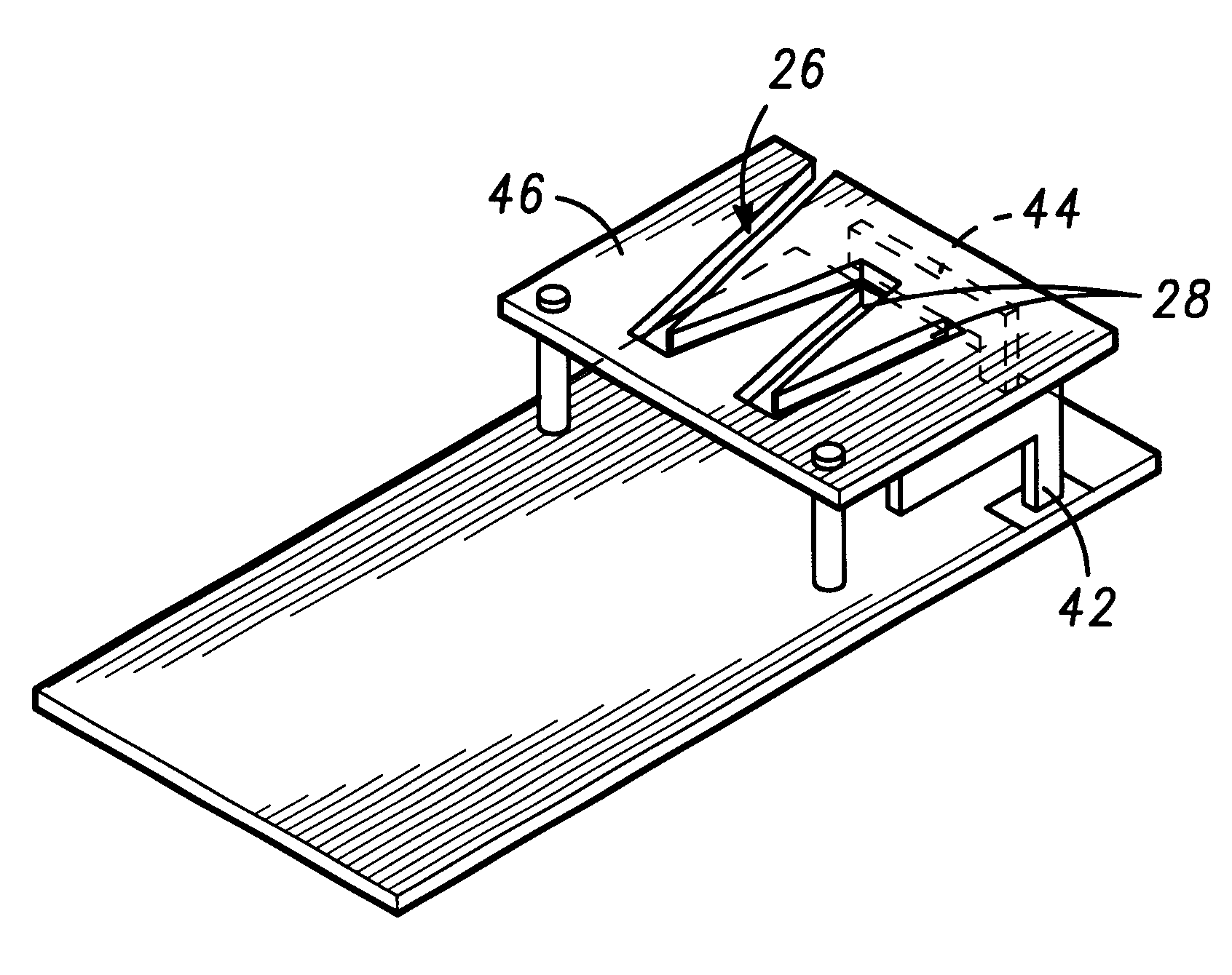
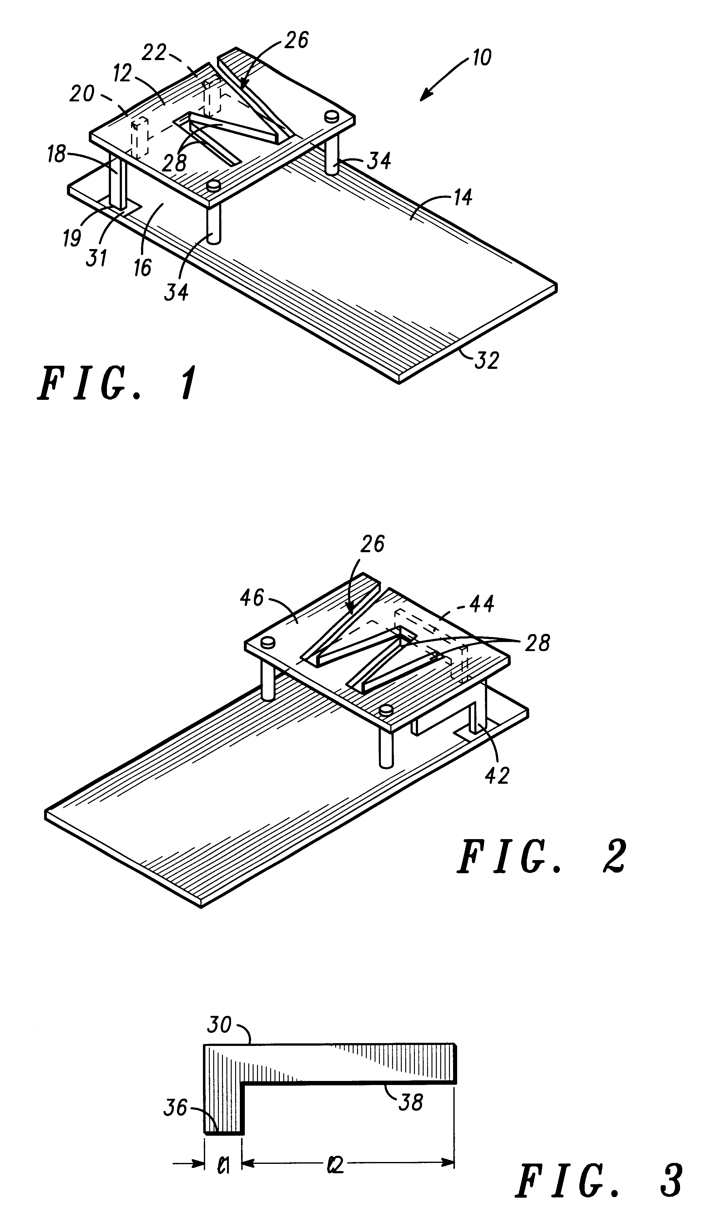
FIG. 1 is a multi-band antenna for use in mobile communication devices, and is particularly suitable for applications requiring a small form factor, for example cellular telephones and other wireless enabled mobile communication devices.

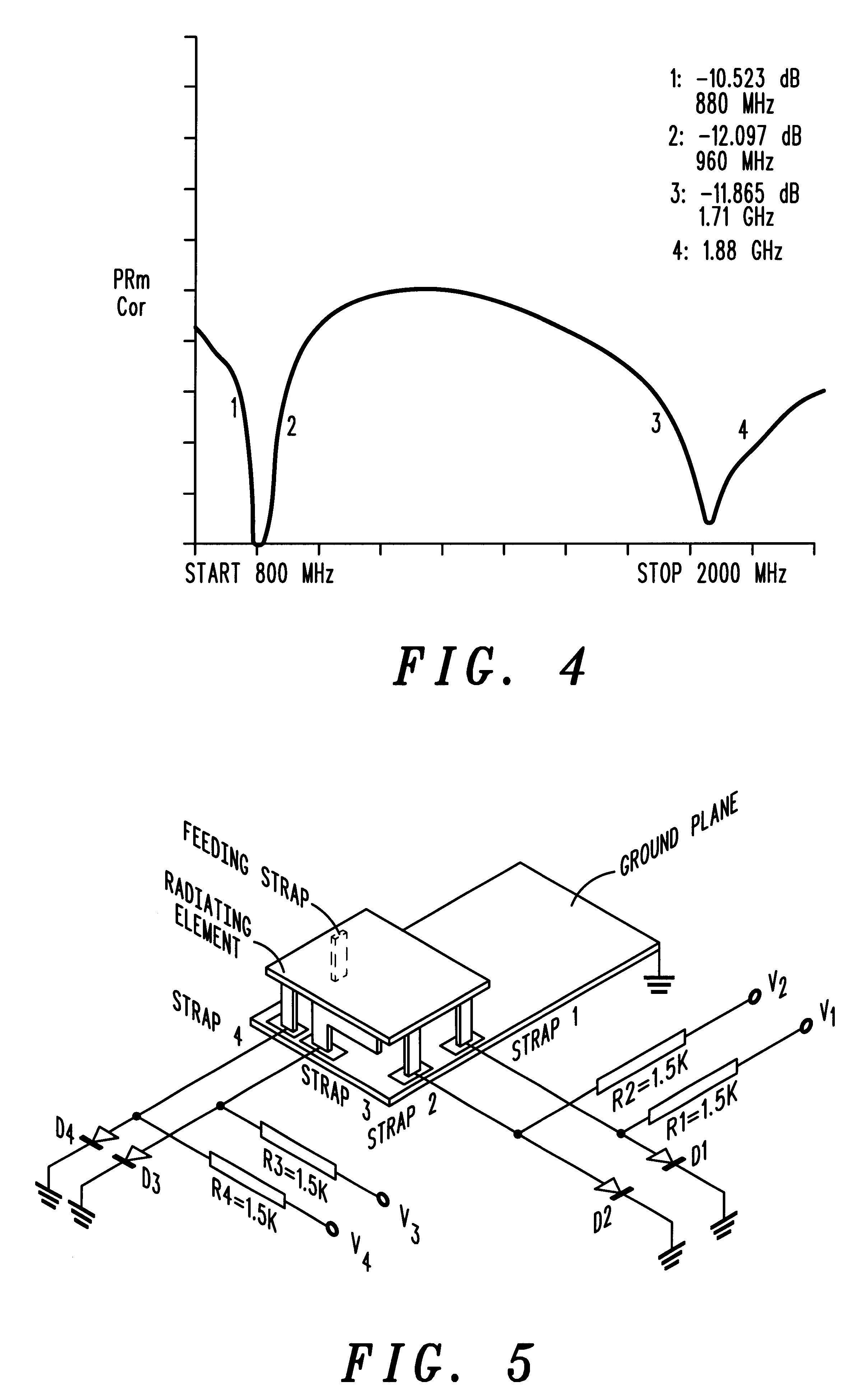
In one embodiment, the multi-band antennas described herein accommodate two or more distinct frequency bands of operation with a single excitation port. The multi-band antenna devices employ shorting straps and a slot to generate multi-band band frequencies with a size and weight much smaller than conventional antennas. An exemplary embodiment described herein generates GSM 900 MHZ frequency and DCS 1800 MHZ frequency, as discussed more fully below.

FIG. 1 illustrates an internal multi-band antenna comprising generally a substantially planar radiating element 12 and a substantially planar ground conductor 14 disposed substantially parallel to the radiating element 12 to serve as a ground plane. In one embodiment, the ground conductor 14 is a conductiv...


PUM


Abstract

An internal multi-band antenna (10) for a mobile communication devices having a planar radiating element (12) and a ground plane conductor (14) disposed substantially parallel thereto with a dielectric (16) such as air or a substrate therebetween. The radiating element (12) includes at a feed point, for example, a feeding strap (18), which may have an L-shape. One or more shorting straps (20,22) are selectively connected between the radiating element (12) and the ground conductor (14), positioned relative to the feed point for tuning the input impedance at the feed point, and for tuning the resonant frequency of the planar radiating element (12). The radiating element includes an angled slot (26) having at least three slot sections, for example, N, M, W shapes and the like, mutually coupled at a second resonant frequency to increase resonant frequency bandwidth. The feeding strap (18) and one or more shorting straps may be provided as inverted L straps (30) for a series LC impedance.

Description

FIELD OF THE INVENTIONSThe present inventions relate generally to antenna devices, and more particularly to internal multi-band slot antennas for mobile communication devices and other compact antenna applications.BACKGROUND OF THE INVENTIONSDual band antennas are used widely in mobile telephones to accommodate different communication standards. Known external dual band antennas, also referred to as stubby antennas, however, tend to exhibit a high Specific Absorption Rate (SAR) compared to other conventional antennas. Additionally, external and retractable antennas are exposed outside the telephone housing, which is inconvenient for the user. Internal antennas have been proposed to replace external and retractable antennas, but conventional internal antenna designs have do not provide adequate bandwidth, especially for dual mode applications.Patch micro-strip antennas are considered advantageous in several ways because of their compact lightweight structure, which is relatively easy...

Claims


Application Information

Patent Timeline
Patent Type & Authority Patents(United States)
IPC IPC(8): H01Q1/24H01Q5/00H01Q9/04H01Q5/371
CPCH01Q1/243H01Q9/0421H01Q5/371H01Q9/14H01Q9/045H01Q1/38
Inventor ZHOU, GUANGPING
Owner MALIKIE INNOVATIONS LTD
Why Eureka
Try Eureka