
Enhancing a video of an event at a remote location using data acquired at the event

a technology for remote locations and events, applied in television systems, closed-circuit television systems, color signal processing circuits, etc., can solve problems such as system failure to make cost-effective use of equipment, equipment is very expensive, and trucks include expensive video equipment and computers

Inactive Publication Date: 2002-10-15
SPORTSMEDIA TECH CORP
View PDF49 Cites 81 Cited by
  • Summary
  • Abstract
  • Description
  • Claims
  • Application Information

AI Technical Summary

Benefits of technology

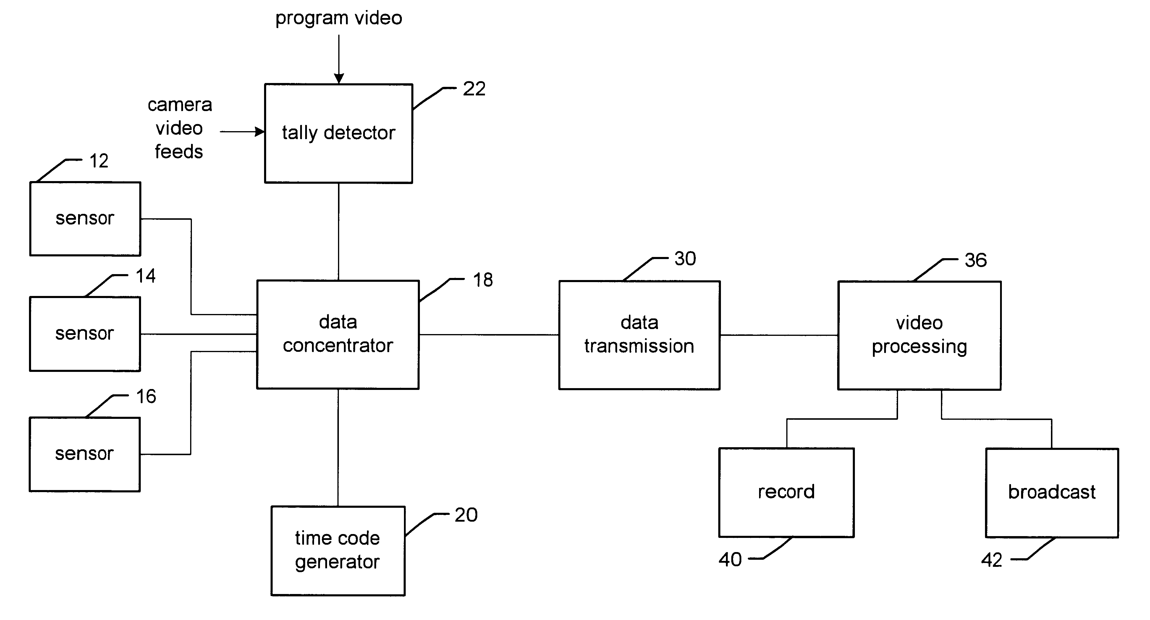
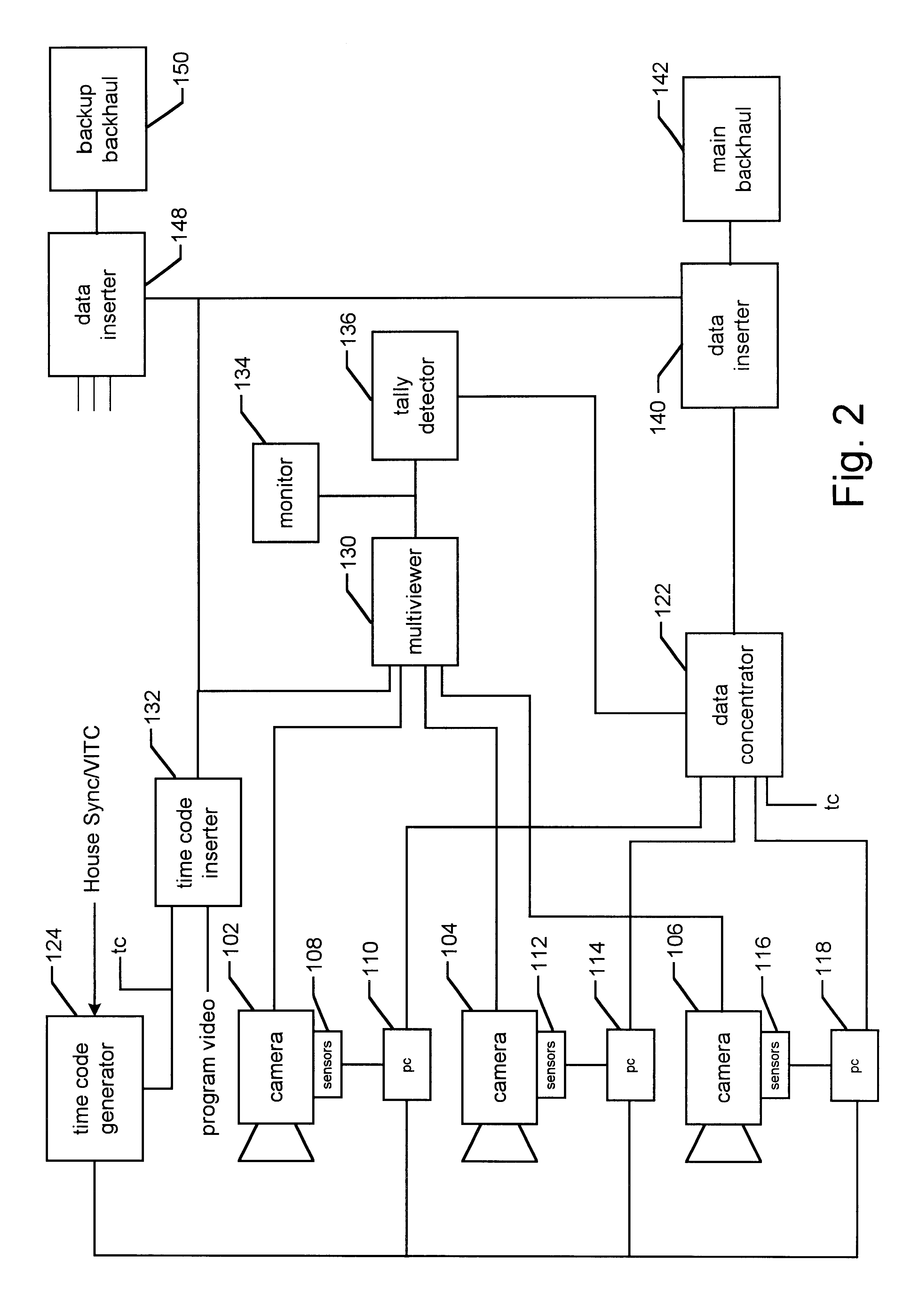
The program video is communicated to multiviewer 130. In one embodiment, the cameras output an analog signal. In another embodiment, the cameras output a digital video signal. In another embodiment, the cameras output analog signals which are converted to digital signals. The system can work with analog signals or digital signals, as long as the appropriate multiviewer is chosen. For example, a multiviewer that can accept digital inputs includes the video Gainsville CVX 64Q. An example of a multiviewer that can accept analog inputs includes the Panasonic WJ-420 quad unit or FOR-A MB-40E. Using digital signals may improve the performance of tally detector 136. Multiviewer 130 combines input video signals into one signal which is sent to tally detector 136 and monitor 134. A suitable multiviewer can be used with less than four or more than four signals. Alternatively, if the tally detector can receive more than one input, there may not be a need for multiviewer. Monitor 134 (optional) is used by an operator to monitor the video signals being sent to tally detector 136.
The system also includes a back up backhaul 150, which is also a standard known in the television industry. Typically, back up backhaul 150 will also transmit the same video signal as main backhaul 142. Back up backhaul 150 is used in case main backhaul 142 fails. Back up backhaul can transmit video by any of the means described for the main backhaul. The system of FIG. 2 also includes a second data inserter 148. Data inserter 148 can insert the camera view data, other target data, registration data, tally indication and / or time codes into the video signal for backhaul 150. In an alternative embodiment, data inserter 148 can be used to insert all or some of the video signals not tallied into back up backhaul data stream. In one embodiment, each of the video signals not tallied can be telemetered via the back up backhaul data stream by using known compression techniques which reduce the quality and / or resolution of the video. In one embodiment, it is acceptable if the video signals being telemetered via the back up backhaul are lower in quality because these signals will only be used for reference purposes.
In another embodiment, rather than determine the position within the video and enhance the video during the live event, the video and all the data is recorded by recorder 178 (and, optionally recorder 184) using a video tape, or other medium. The components of FIG. 3 can be used to perform the steps of FIG. 7 subsequent to the end of the event in order to post process the video tape. By recording all of the camera view data, time codes and registration information, the system of FIG. 3 can easily post process the data.
Additionally, because the equipment depicted in FIG. 3 is located at a studio remote from the event, immediately following the end of the event the equipment of FIG. 3 can be used for another event. The equipment does not need to be transported before subsequent use and the broadcaster need not purchase an expensive truck to transport the equipment. In one alternative, the processors depicted in FIG. 3 can be large main frames or super computers so that more than one event can be processed at the same time. It is also contemplated that a studio complex can have multiple studios within the complex for simultaneously processing / broadcasting many events. Each studio can contain the components of FIG. 3 so that multiple events can be processed and broadcast at the same time.

Problems solved by technology

Typically, such trucks include expensive video equipment and computers.
While the above-described arrangement has been successful in providing various graphical effects, such an arrangement has its drawbacks because the equipment is very expensive and the systems do not make cost efficient use of the equipment.
Purchasing four sets of equipment can be very expensive for a broadcaster and the trucks to house / transport the equipment are expensive.
Additionally, a broadcaster may not have four sets of equipment available.
During transport, the equipment is not available for use by the broadcaster.
Additionally, repeatedly transporting the equipment adds to the maintenance costs of the equipment.
In sum, broadcasters spend large amounts of money for equipment that is not available at all times and has high maintenance costs.
Because there may be different delays due to processing the data or blending a graphic, and because the data may be stored for future post processing, it is necessary in some embodiments to associate time codes with the data and the video.
The delay cannot grow as the event progresses.

Method used


Image

  • Enhancing a video of an event at a remote location using data acquired at the event
  • Enhancing a video of an event at a remote location using data acquired at the event
  • Enhancing a video of an event at a remote location using data acquired at the event

Examples


Embodiment Construction

has been presented for purposes of illustration and description. It is not intended to be exhaustive or to limit the invention to the precise form disclosed, and obviously many modifications and variations are possible in light of the above teaching. The described embodiments were chosen in order to best explain the principles of the invention and its practical application to thereby enable others skilled in the art to best utilize the invention in various embodiments and with various modifications as are suited to the particular use contemplated. It is intended that the scope of the invention be defined by the claims appended hereto.


PUM


Abstract

A system is disclosed that can be used to enhance a video of an event. Sensors are used at the event to acquire information. For example, the system can include pan, tilt and zoom sensors to acquire camera view information. This information can be added to the video signal from a camera (e.g. in the vertical blanking interval) or otherwise transmitted to a central studio. At the studio, the sensor information is used to enhance the video for broadcast. Example enhancements include drawing lines or other shapes in the video, adding advertisements to the video or adding other graphics to the video.

Description

1. Field of the InventionThe present invention is directed to a system for enhancing a video of an event using data acquired at the event.2. Description of the Related ArtThe remarkable, often astonishing, physical skills and feats of great athletes draw millions of people every day to follow sports that range from the power of American football to the grace of figure skating, from the speed of ice hockey to the precision of golf. Sports fans are captivated by the abilities of basketball players to soar to the rafters, a baseball batter to drive the ball out of the park, a runner to explode down the track, a skier to race down the hill, a running back to break through the pack and make the first down, etc. In televising these events, broadcasters have developed a wide repertoire of technologies--ranging from slow-motion replay to lipstick-sized cameras mounted on helmets--to highlight for viewers these exciting events. Other examples of technologies used by the broadcasters include ...

Claims


Application Information

Patent Timeline
IPC IPC(8): H04N7/087H04N7/088H04N5/222
CPCH04N5/222H04N7/088
Inventor HONEY, STANLEY K.CAVALLARO, RICHARD H.GEPNER, JERRY N.GLOUDEMANS, JAMES R.WHITE, MARVIN S.
Owner SPORTSMEDIA TECH CORP
Learn More