Fuel injector

a fuel injector and fuel technology, applied in the direction of machines/engines, mechanical equipment, lighting and heating apparatus, etc., can solve the problems of reducing stability, difficult to achieve engine ignition, and soot and smoke emission

Inactive Publication Date: 2002-11-05
QINETIQ LTD
View PDF13 Cites 67 Cited by
  • Summary
  • Abstract
  • Description
  • Claims
  • Application Information

AI Technical Summary

Benefits of technology

It is an object of the invention to provide flow mixing control at the fuel injector stage which can vary the air flow (or fuel) in a reliable and controllable manner.
According to the invention is provided a fuel injector including a combustion air flow conduit, a fuel inlet, means to mix the air and fuel flowing therethrough, and fluidic control means including at least one control port, such that variation of flow of control air through said control port allows variation in the degree of flow resistance to which combustion air is subjected.
The advantage of such:a design of fuel injector is that it does not require moving parts and as such is inherently robust.
A typical modern fuel injector includes a number of swirlers. The swirling flow from the injector is required to form aerodynamic recirculation. Varying the swirl will vary the strength of the recirculation zones within the combustor, thus varying flow resistance. Preferably the fluidic control means allows variation in the degree of swirl to be varied.

Problems solved by technology

An ideal air / fuel mixture ratio at cruise usually leads to an over rich mixture in the burning zone at high power conditions (such as take-off) with resultant soot and smoke emission.
It is possible to reduce smoke emission at take-off by weakening the burning zone mixture strength but this involves an increase in primary zone air flow which reduces stability and makes ignition of the engine difficult to achieve, especially at altitude.
However at low temperatures, the efficiency of the overall cycle is reduced.
Although the reduction in fuel flow is almost instantaneous, the rate of reduction of engine airflow is relatively slow because of the inertia of rotating parts such as turbines, compressors, shafts etc.
This is produces a weak mixture of fuel and this increases the risk of flame extinction, especially at altitude.
It is not always easy to relight the flame especially when the combustor is set to run weakly.
If margins are set wide enough to prevent flame extinction, emissions performance is compromised.
These combustor designs will also suffer from either high nitrogen oxide and / or smoke emissions at full power, or poor stability at low power.
At idle, with airblast atomiser fuel injectors, low airflow results in low air velocity through the injector.
Such designs have not found favour as they are not robust.
In the high temperature atmosphere of the combustor and due to the complex nature of fuel injectors, moving parts are unreliable.
It is therefore impractical to use such devices in a working gas turbine engine.

Method used


Image

  • Fuel injector
  • Fuel injector
  • Fuel injector

Examples


Embodiment Construction

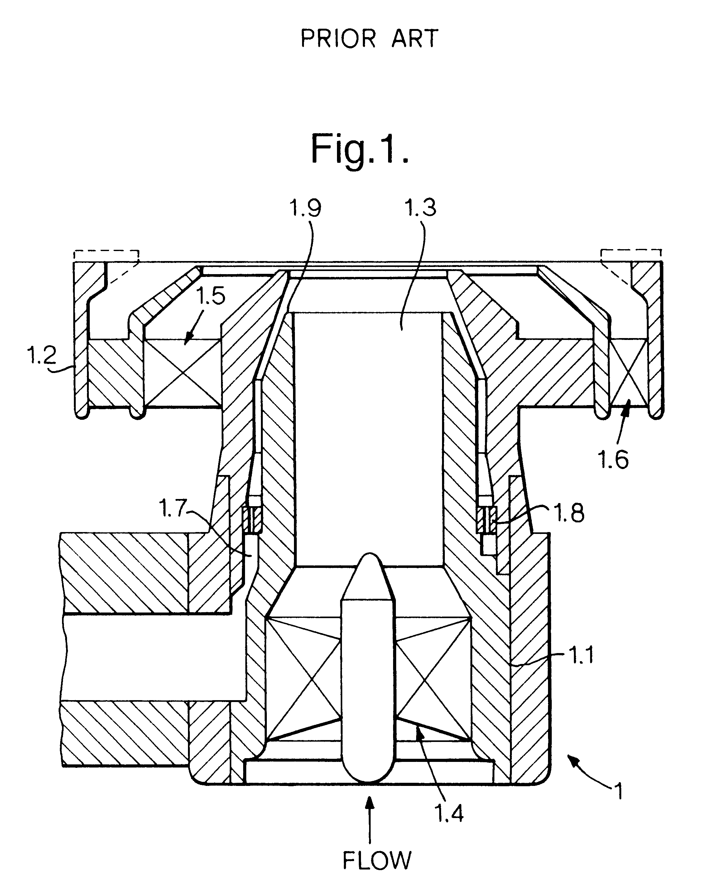
FIG. 1 shows a cross sectional view of a conventional fuel injector 1 for a gas turbine, comprising a main housing 1.1 and a collar 1.2 located at the end which is fitted to the combustor primary zone. Within the body is located an inner flow conduit 1.3 through which a fixed proportion of compressed air flows in the direction of the arrow and located within this is an inner air swirler 1.4. The remainder of the compressed air flows around the main body and through two annular concentric conduits each comprising a swirler which form the collar, these being referred to as "outer" and "dome" swirlers, 1.5 and 1.6 respectively. In parallel, fuel is fed into the fuel injector, through a fuel channel 1.7 and then through a fuel swirler 1.8 where it is vigorously agitated. The fuel then passes over a prefilmer 1.9 positioned concentrically about the inner air swirler 1.4 from where it is expelled from the fuel injector and mixes with turbulent air expelled from the air swirlers prior to i...


PUM


Abstract

A fuel injector including a combustion air flow conduit, a fuel inlet and, swirlers to mix the air and fuel flowing therethrough, additionally comprising fluidic control diverters including at least one control port, such that flow of control air through said control port allows variation in the degree of flow resistance to which combustion air is subjected. For example, control air flowing through the control port may impart swirl to the combustion air flow from the inlet, thereby subjecting the combustion air flow to increased resistance. Alternatively a fluidic diverter may selectively divert the main flow to either the first or second sub-conduits, each sub-conduit subjecting combustion air to different degrees of flow resistance.

Description

1. Field of the InventionThe invention relates to fuel injectors wherein air and fuel are mixed before combustion. It has particular application to fuel injectors used for combustors in gas turbine engines.2. Discussion of Prior ArtGas turbine engines include an air intake through which air is drawn and compressed by a compressor and thereafter enters a combustor at one or more ports. Fuel is injected into the combustion chamber by means of a fuel injector where it mixed with compressed air from the various inlet ports and burnt. Exhaust gases are passed out of an exhaust nozzle via a turbine which in turn drives drive the compressor. In addition to air flow into the combustion chamber through the air inlet ports, air also enters the combustion chamber via the fuel injector itself. The fuel injector is therefore different from fuel injectors in Diesel engines, for example, in that air is mixed with fuel before entering the combustion chamber. Fuel injectors therefore provide an air / ...

Claims


Application Information

Patent Timeline
Patent Type & Authority Patents(United States)
IPC IPC(8): F15C1/08F15C1/00F23R3/02F23R3/26F23C7/00F23C99/00
CPCF15C1/08F23C7/008F23R3/26F05D2270/18Y10S239/03
Inventor BRUNDISH, KEVIN D.WILSON, CHRISTOPHER W.TIPPETTS, JOHN R.
Owner QINETIQ LTD
Why Eureka
Try Eureka