Tire pressure display device

a display device and tire pressure technology, applied in the direction of transmission system, tyre measurement, indirect connection of subscribers, etc., can solve the problems of complex and expensive retrofitting of vehicles with such high-frequency cables, inability to activate module means upon demand, and high cos

Inactive Publication Date: 2002-11-05
RAINER ACHTERHOLT
View PDF3 Cites 67 Cited by
  • Summary
  • Abstract
  • Description
  • Claims
  • Application Information

AI Technical Summary

Benefits of technology

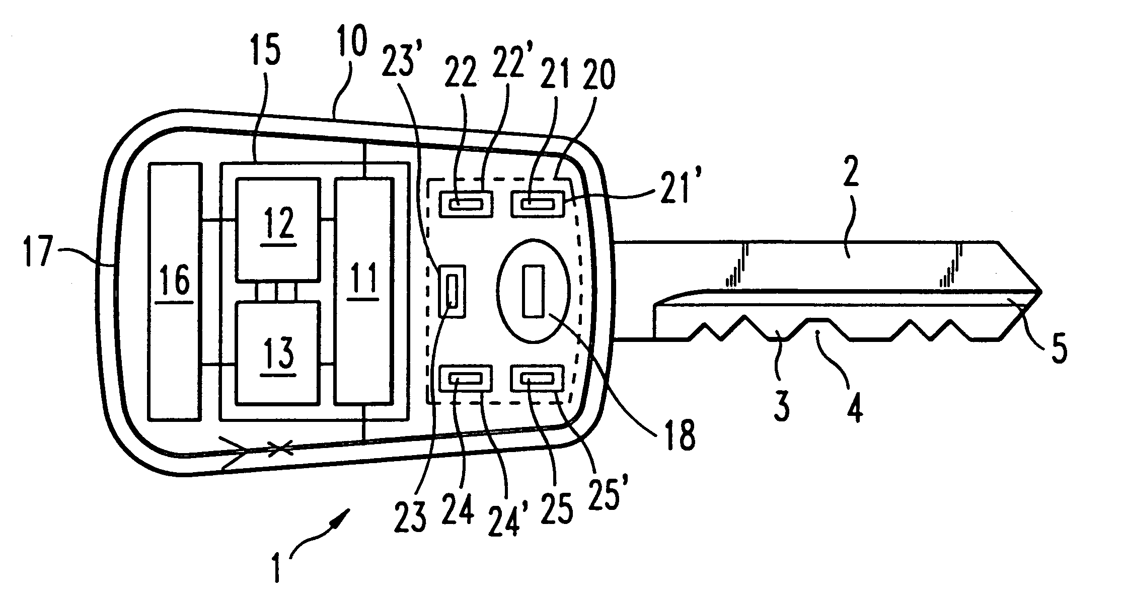
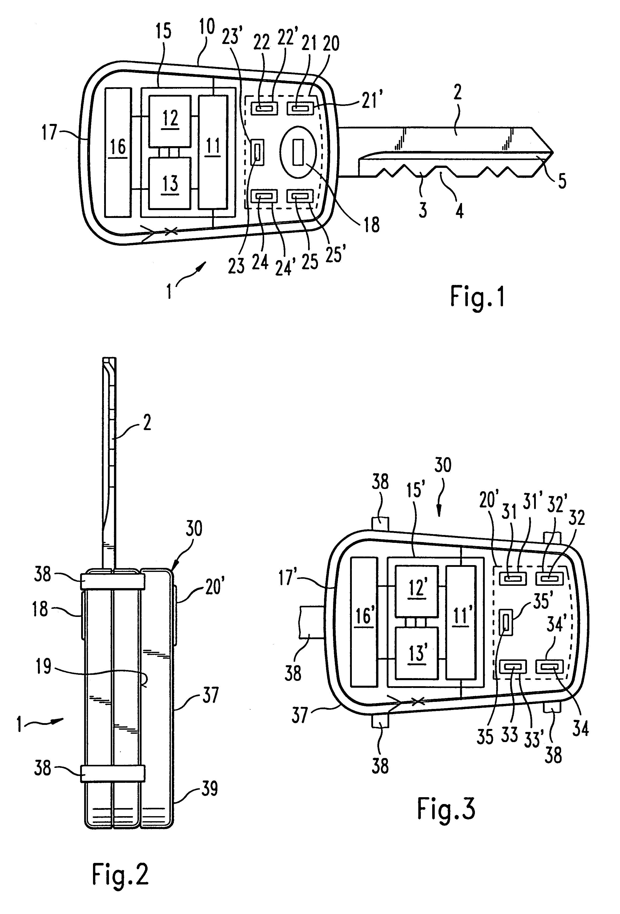
The objective of the present invention is to create a tire pressure display device of the type described above (see U.S. Pat. No. 4,376,931) that is simpler and less expensive in terms of complexity and function.
This modification yields an even greater security in the transmission and assignment of the data signals.

Problems solved by technology

Experience has shown that the hard-wired transmission of the radiograms received at the vehicle's antennas to a central evaluation means calls for special (and expensive), shielded high-frequency cables.
Retrofitting a vehicle with such high-frequency cables is complicated and expensive.
However, it is not possible to activate the module means upon demand at a specific point in time, since said means does not have a receiver for high-frequency signals.
However, this document does not recognize and propose feeding the display signals that have been generated by the master means to the electronic key and displaying them by means of display devices that are situated on the electronic key.
The known remote control element has no other functions; in particular, it is not designed to generate wirelessly transmittable signals for a remote control locking system in the vehicle.
However, as far as the inventor knows, up until now, such an "electronic vehicle key" has not yet been used to display the tire pressure of the wheels of a vehicle.

Method used


Image

  • Tire pressure display device
  • Tire pressure display device

Examples


Embodiment Construction

According to the invention, the interrogation and display of the tire pressure are carried out while the vehicle is stationary each time before it is driven by actuating the remote control locking means to open at least one vehicle door. This is considered to be sufficient since the development of tires, rims and valves has reached such a high quality standard that the main cause of improper tire pressure is due to gradual pressure loss. In comparison to this, an additional and constant monitoring of the tire pressure on the moving vehicle would only negligibly increase the safety but it quite considerably increases the complexity and costs.

The management according to the invention for checking the tire pressure avoids the high-frequency communication between the master means and the module means that takes place at regular intervals. In particular, this increases the useful service life of the power supply source on the wheel. Moreover, a higher field strength can be provided for t...


PUM


Abstract

A tire pressure display device for a vehicle having several wheels provides each monitored tire with an electronic module including, for example, an integrated pressure sensor with measuring and control electronics which are coupled to a high-frequency transmitter / receiver. Away from the wheels, there is at least another high-frequency transmitter / receiver that is coupled to a microprocessor that exchanges high-frequency radiograms with each wheel's electronic module in an interrogation-response mode. In addition, a remote control locking arrangement activates a locking system on the vehicle. The triggering of a control command effectuated on the remote control locking arrangement also activates the microprocessor, which then initializes the electronic module for each monitored tire.

Description

1. Field of the InventionThe present invention relates to a tire pressure display device for a vehicle having several wheels, each of which is fitted with a pneumatic tire, whereby each monitored tire is provided with an electronic module having at least one integrated pressure sensor with measuring and control electronics, said sensor being coupled to a high-frequency transmitter / receiver means (in short: module means); away from the wheels, there is at least another high-frequency transmitter / receiver means coupled to a microprocessor (in short: master means), which is configured for bi-directional high-frequency signal-data communication with each module means in the interrogation-response mode; the tire pressure status of each monitored tire is displayed on one or more display element(s) of a display device that is actuated by display signals that have been generated by the microprocessor.Furthermore, the invention relates to a vehicle remote control locking means intended for v...

Claims


Application Information

Patent Timeline
Patent Type & Authority Patents(United States)
IPC IPC(8): B60C23/04B60C23/02
CPCB60C23/0401B60C23/0408B60C23/0479
Inventor ACHTERHOLT, RAINER
Owner RAINER ACHTERHOLT
Why Eureka
Try Eureka