Method and system for eliminating artifacts in overlapped projections

a technology of overlapped projection and artifacts, applied in the field of projection systems, can solve the problems of non-linear mapping of pixel values to intensities, visible seams, and inability to produce perfectly black pixels in the real world (e.g., practical) projectors

Inactive Publication Date: 2002-11-12
LENOVO PC INT
View PDF9 Cites 89 Cited by
  • Summary
  • Abstract
  • Description
  • Claims
  • Application Information

AI Technical Summary

Problems solved by technology

Unfortunately, "real-world" (e.g., practical) projectors cannot produce perfectly black pixels.
This is due, for example, to imperfections in the light valves used in liquid crystal display (LCD) projectors or residual phosphorescence in cathode ray tube (CRT) projectors.
Such seams are visually distracting and can potentially convey information to the viewer that is not part of the image but purely an artifact of the overlapping tiles.
Further, real mappings from pixel values to intensities also are frequently non-linear.
It is noted that the pixel intensities in the overlap area are too large, thereby creating the effect of visible seams in the composite image.

Method used


Image

  • Method and system for eliminating artifacts in overlapped projections
  • Method and system for eliminating artifacts in overlapped projections
  • Method and system for eliminating artifacts in overlapped projections

Examples


embodiment

PREFERRED EMBODIMENT

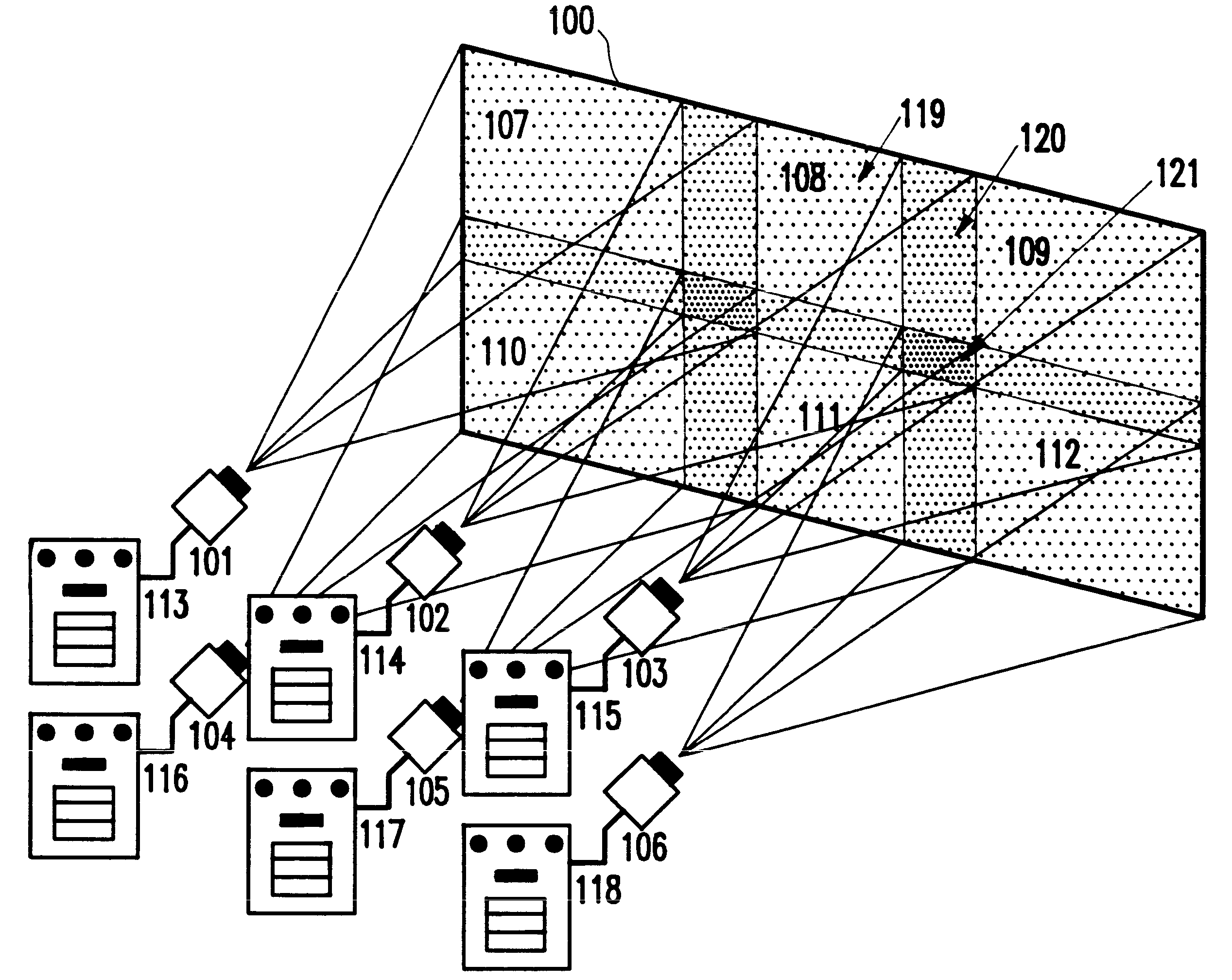
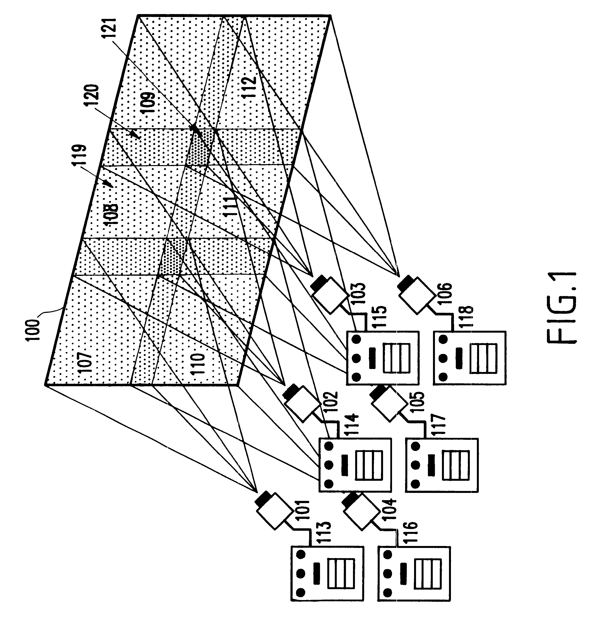
To eliminate the above-mentioned problem and other problems of the conventional systems and methods, the invention generally takes the following basic approach.

First, in areas outside of the overlap areas, the intensity of black pixels is raised to match the black level in the overlap areas. Thereafter, the pixel values are scaled in the overlap areas such that they never exceed the maximum pixel value of a single projector. In practice, the maximum pixel value is usually limited to either 1.0 or 255 (e.g., for 8 bits). It is noted that the above-described sequence may be reversed. That is, the scaling of the white pixels may be performed first, and then in areas outside of the overlap areas, the intensity of black pixels may be raised to match the black level in the overlap areas.

Hereinbelow, the following conventions and symbols will be used:

It is noted that "pixel value" is different from "intensity". That is "pixel value" refers to the input to the system, wh...


PUM


Abstract

A method (and system) of eliminating visible artifacts in overlapped projections produced by a plurality of projectors, includes in areas outside of the overlap areas, raising an intensity of predetermined color pixels to match a level of the predetermined color in the overlap areas, and simultaneously with the raising of the intensity, scaling values of pixels in the overlap areas such that the values do not exceed the maximum pixel value of a single projector of the plurality of projectors.

Description

1. Field of the InventionThe present invention generally relates to a projection system, and more particularly to a method and system for eliminating artifacts in overlapped projections.2. Description of the Related ArtRecently, large display walls have been constructed using multiple projectors that each project their images onto a large screen. Typically, each projector in such a system provides parts of the image, thus composing the image from several "tiles".To avoid visible seams (e.g., discontinuities) in the composite image, projectors are typically arranged such that their projected images slightly overlap. Pixels in the overlapping areas are attenuated such that their relative contributions add up to 1. Thus, each projector provides a certain percentage (e.g., a relative contribution) of the final pixel color / intensity. Thus, ideally (e.g., in theory), such attenuation makes the overlap areas invisible to a viewer. That is, black pixels (e.g., having a value of 0) must be p...

Claims


Application Information

Patent Timeline
Patent Type & Authority Patents(United States)
IPC IPC(8): G06F3/14G09G5/10H04N9/12H04N17/04G09G5/00G09G3/00H04N17/00H04N5/74
CPCG06F3/1446G09G5/10H04N9/12H04N9/3147H04N9/3194H04N17/04G09G3/001G09G5/00G09G2320/0233G09G2340/10
Inventor SCHNEIDER, BENGT-OLAF
Owner LENOVO PC INT
Why Eureka
Try Eureka