Method for precision bending of a sheet of material and slit sheet therefor

a technology of slit sheet and material, which is applied in the direction of metal-working feeding device, forging/pressing/hammering apparatus, handling devices, etc., can solve the problems of accumulation of tolerance errors, difficult control of bend locations, and significant cumulative tolerance errors in bending, so as to reduce stress concentration and reduce stress concentration.

Inactive Publication Date: 2002-11-19
IND ORIGAMI INC CA US
View PDF13 Cites 167 Cited by
  • Summary
  • Abstract
  • Description
  • Claims
  • Application Information

AI Technical Summary

Benefits of technology

In another aspect, the method of the present invention includes slitting a sheet of material for precision bending which comprises the steps of forming a first elongated slit through the sheet of material along the bend line by forming a pair of proximate, transversely spaced apart, parallel and longitudinally extending, first slit segments connected near a common transverse plane by a transversely extending slit segment; and forming a second elongated slit in substantially longitudinally aligned and longitudinally spaced relation to the first elongated slit. The step of forming the second elongated slit also preferably is accomplished by forming a pair of proximate, transversely spaced apart, parallel and longitudinally extending, slit segments connected near a common transverse plane by a transversely extending slit segment. Thus, instead of one continuous elongated slit, each slit in the pair of slits is formed as a slightly stepped slit proximate a midpoint of the combined length of the slit segments. This structure produces a virtual fulcrum upon bending that can be p

Problems solved by technology

A commonly encountered problem in connection with bending sheet material is that the locations of the bends are difficult to control because of bending tolerance variations and the accumulation of tolerance errors.
The second bend, however, works off of the first bend and accordingly the tolerance errors accumulate.
Since there can be three or more bends which are involved to c

Method used


Image

  • Method for precision bending of a sheet of material and slit sheet therefor
  • Method for precision bending of a sheet of material and slit sheet therefor
  • Method for precision bending of a sheet of material and slit sheet therefor

Examples


second embodiment

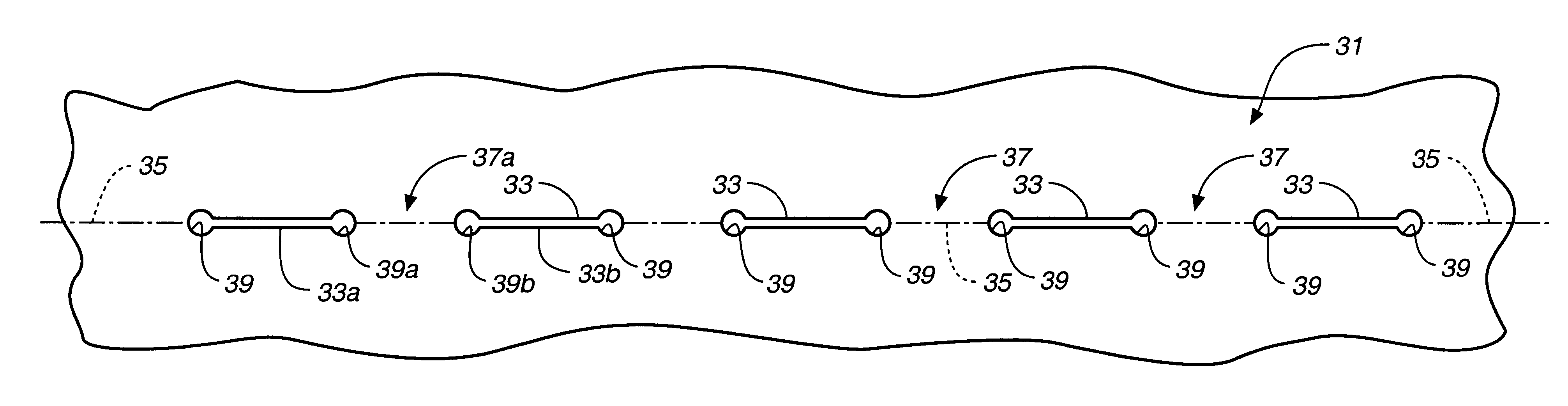
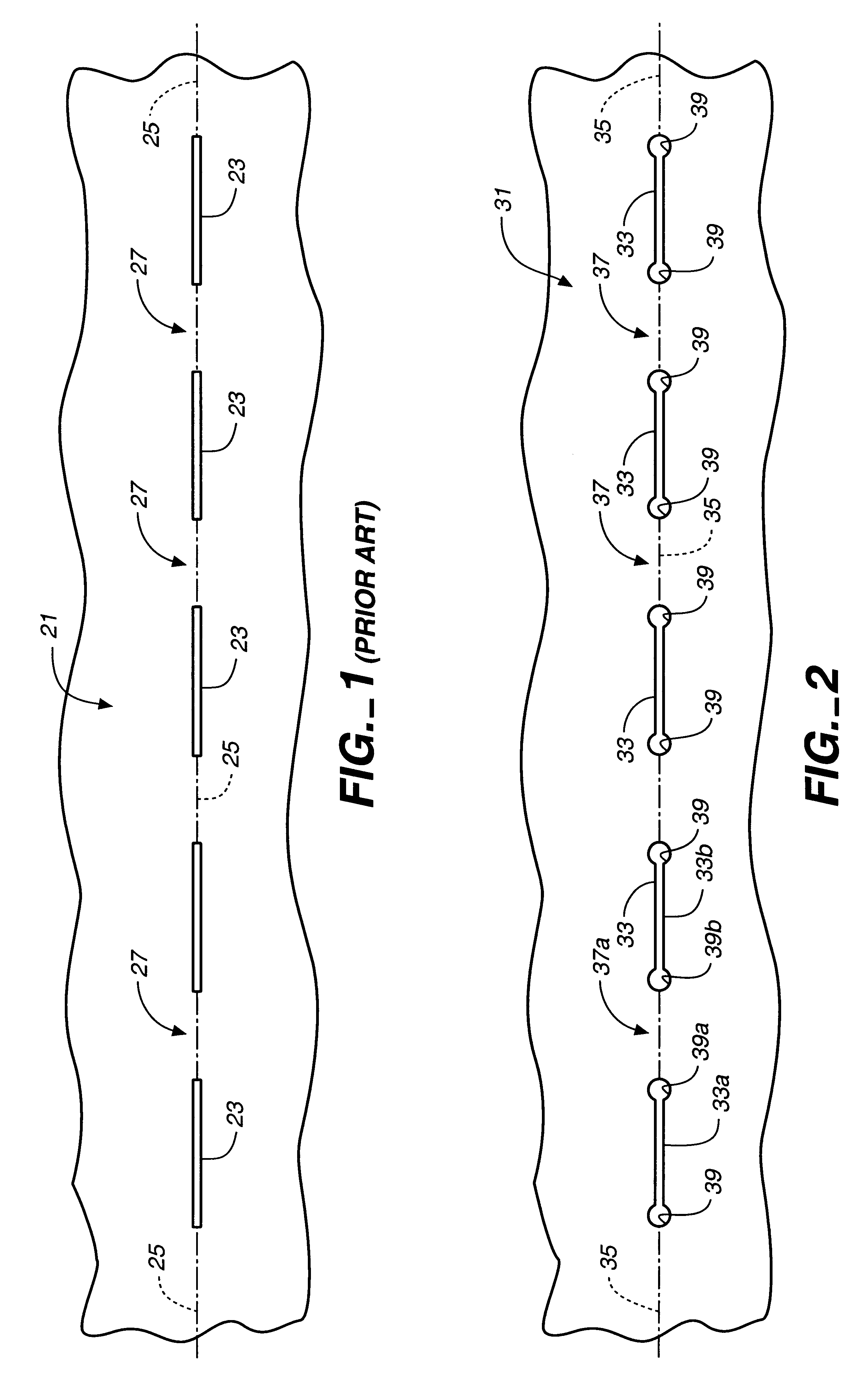
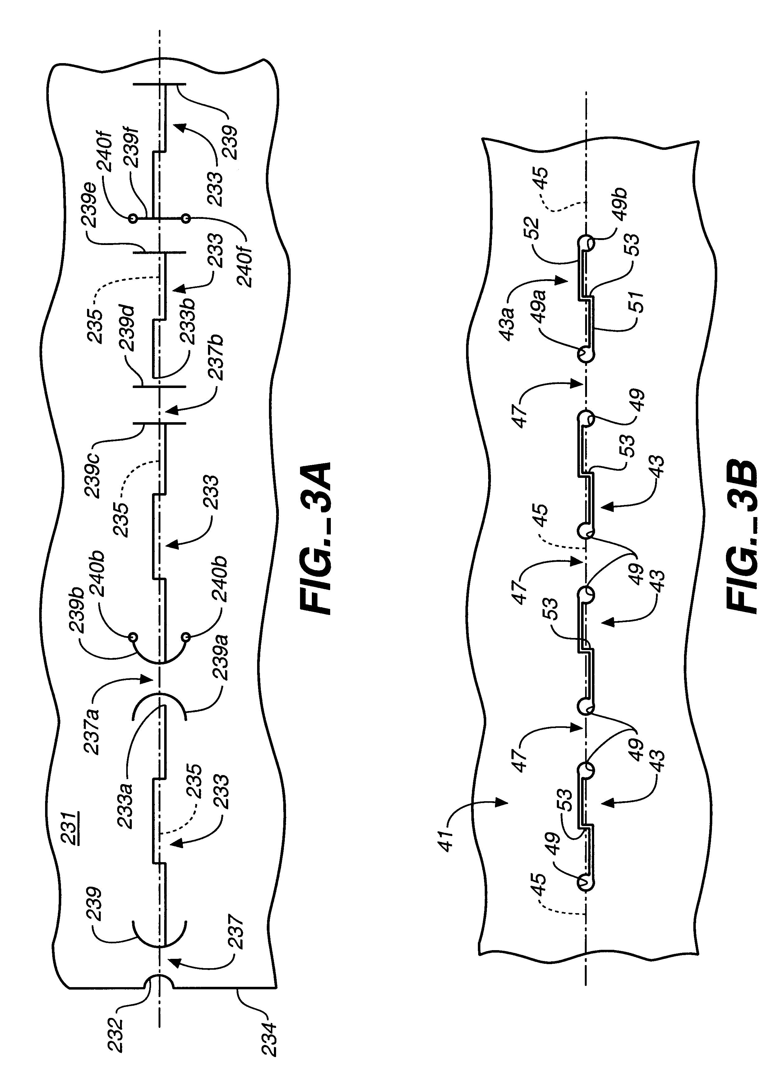
a stress reducing structure is shown in FIG. 3A. A sheet of material 231 is formed with a plurality of aligned longitudinally extending slits 233 extending along a bend line 235. Slits 233 are transversely stepped in a manner which will be described in more detail hereinafter.

Positioned at the adjacent ends of slits 233 are stress reducing structures 239, which in the embodiment of FIG. 3A are provided as transversely extending slits. In the most preferred form of slit-based stress reduction structure 239 the slits are transversely extending arcuate slits, such as shown by slits 239a and 239b. As will be seen, these arcuate slits curve back along the respective longitudinally extending slits 233 to which they are connected. Thus, the stress reducing arcuate slits are convex in a direction facing intermediate bending webs 237 and 237a. Bending webs 237 are defined by an arcuate notch 232 at edge 234 of sheet 231 and the adjacent arcuate stress reducing slit 239, or by pairs of slits ...


PUM

PropertyMeasurementUnit
Thicknessaaaaaaaaaa
Shapeaaaaaaaaaa
Widthaaaaaaaaaa

Abstract

A method for precision bending of a sheet of material (31,41,61,91,231) along a bend line (35,45,62-66,96,235) and the resulting sheet are disclosed. A method includes a step of forming and longitudinally extending slits (33,43,68,92,233) through the sheet of material in axially spaced relation to define bending webs (37,47,71,72,106,237), forming stress reducing structures such as enlarged openings (39,49,69,73) or transversely extending slits (239) at each of adjacent ends of pairs of slits in order to reduce crack propagation across the bending webs. In another aspect, the elongated slits (43,68,92,233) are formed with pairs of longitudinally extending slit segments (51,52;74,76;98,99;127) proximate to and on opposite sides of and substantially parallel to the desired bend line. Longitudinally extending slit segments further are connected by at least one intermediate transversely extending slit segment (53,77,101,128). Sheets of slit material suitable for bending also are disclosed.

Description

The present invention relates, in general, to the bending of sheets of material, and more particularly, relates to slitting of the sheet material in order to enable precision bending.A commonly encountered problem in connection with bending sheet material is that the locations of the bends are difficult to control because of bending tolerance variations and the accumulation of tolerance errors. For example, in the formation of the housings for electronics, sheet metal is bent along a first bend line within certain tolerances. The second bend, however, works off of the first bend and accordingly the tolerance errors accumulate. Since there can be three or more bends which are involved to create an enclosure, the effect of cumulative tolerance errors in bending can be significant.One approach to this problem is to try to control the location of bends in sheet material through the use of slitting. Slits can be formed in sheet stock very precisely, for example, by the use of computer nu...

Claims


Application Information

Patent Timeline
IPC IPC(8): B21D5/00E04C2/08B21D28/26B21D5/02
CPCB21D5/00B21D35/00E04C2/08Y10T428/24314Y10S229/931E02D17/20E02D17/202B21D28/26
Inventor DURNEY, MAX W.
Owner IND ORIGAMI INC CA US
Why Eureka
Try Eureka