Gasket for pressurized fluid system

a fluid system and gasket technology, applied in fluid pressure sealing joints, cable terminations, mechanical equipment, etc., can solve problems such as failure of gaskets, and achieve the effects of minimizing fluid pressure stress in the gasket, reducing clamping pressure, and reducing pressur

Inactive Publication Date: 2002-11-19
WESTINGHOUSE AIR BRAKE CO
View PDF8 Cites 8 Cited by
  • Summary
  • Abstract
  • Description
  • Claims
  • Application Information

AI Technical Summary

Benefits of technology

A further object of the present invention is to provide an improved combination of flange and gasket for pressurized fluid systems which provides high clamping pressures on the gasket.
It is an additional object of the present invention to provide a gasket for pressurized fluid systems in which stresses in the gasket due to the fluid pressure are minimized.
Still yet another object of the present invention is to provide a gasket for pressurized fluid systems having square flanges in which stresses in the gasket due to the fluid pressure are minimized.
Yet still another object of the present invention is to provide a gasket and flange combination for pressurized fluid systems in which the clamped area of the gasket is minimized to increase clamping pressure.
Yet an additional object of the present invention is to provide a gasket and flange combination for pressurized fluid systems which presents a smooth continuous surface to the fluid to reduce turbulence in the fluid.

Problems solved by technology

These stresses tend to cause failure of gasket 12.

Method used


Image

  • Gasket for pressurized fluid system
  • Gasket for pressurized fluid system
  • Gasket for pressurized fluid system

Examples


Embodiment Construction

, particularly, when the detailed description is taken in conjunction with the attached drawing figures and with the appended claims.

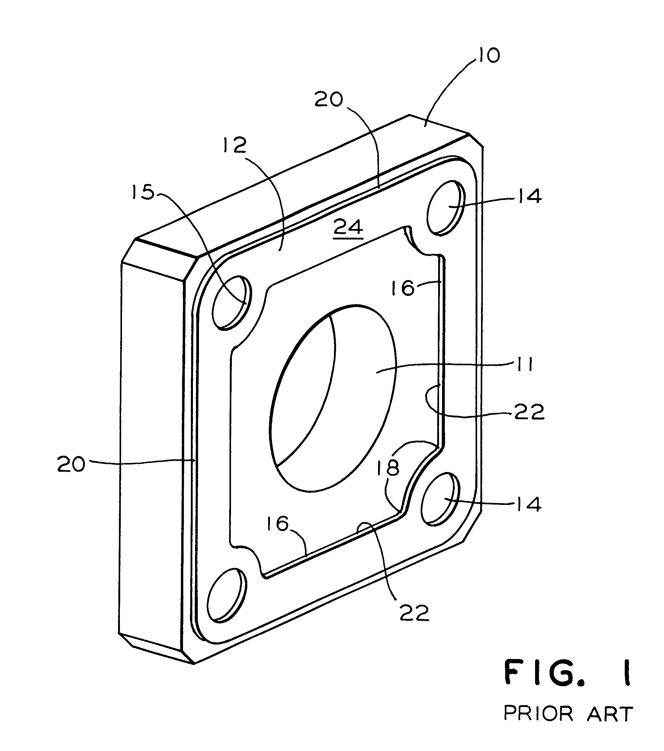
FIG. 1 is a perspective view of a prior art rectangular flange and gasket.

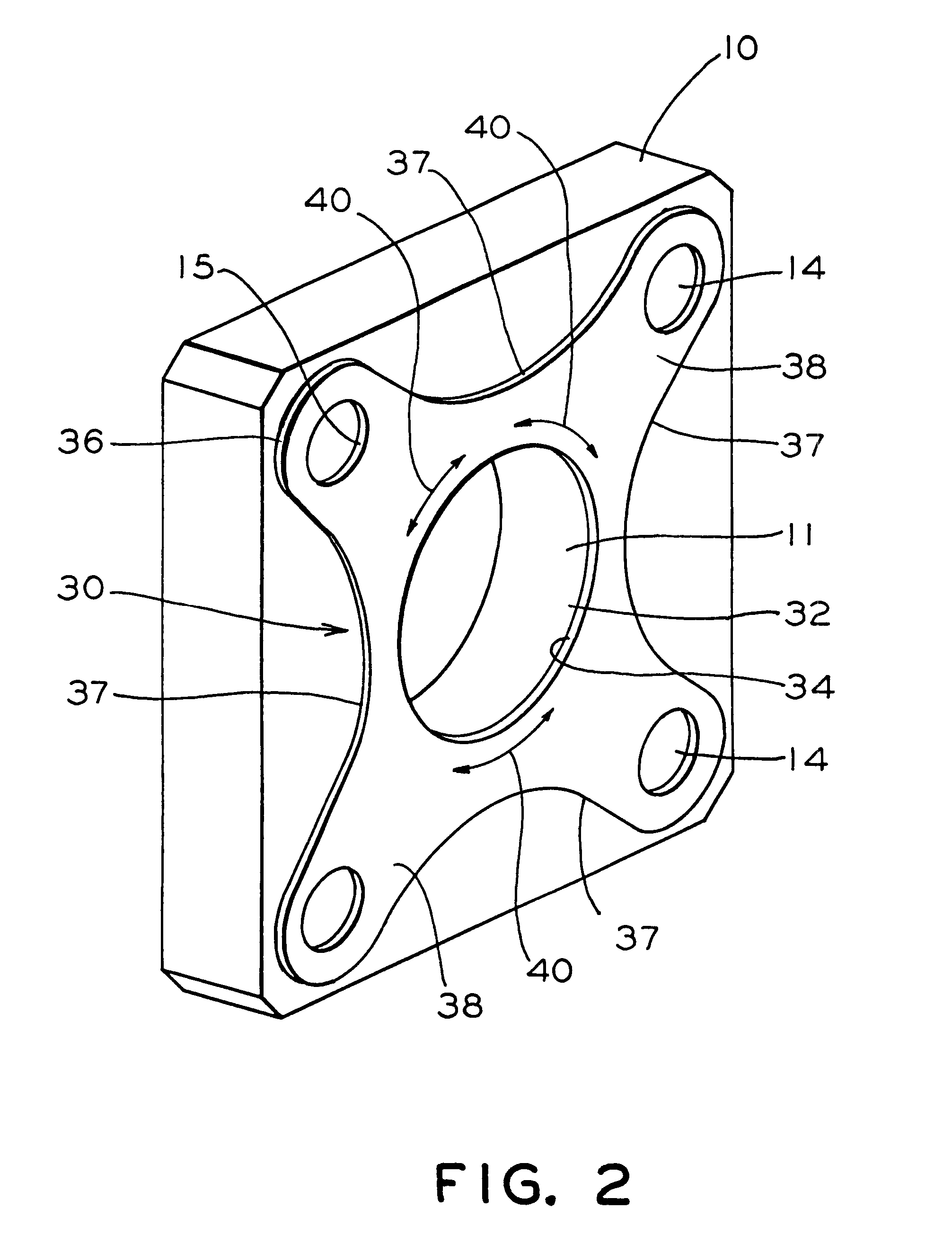
FIG. 2 is a perspective view of a rectangular flange with a presently preferred embodiment of the gasket of the present invention.

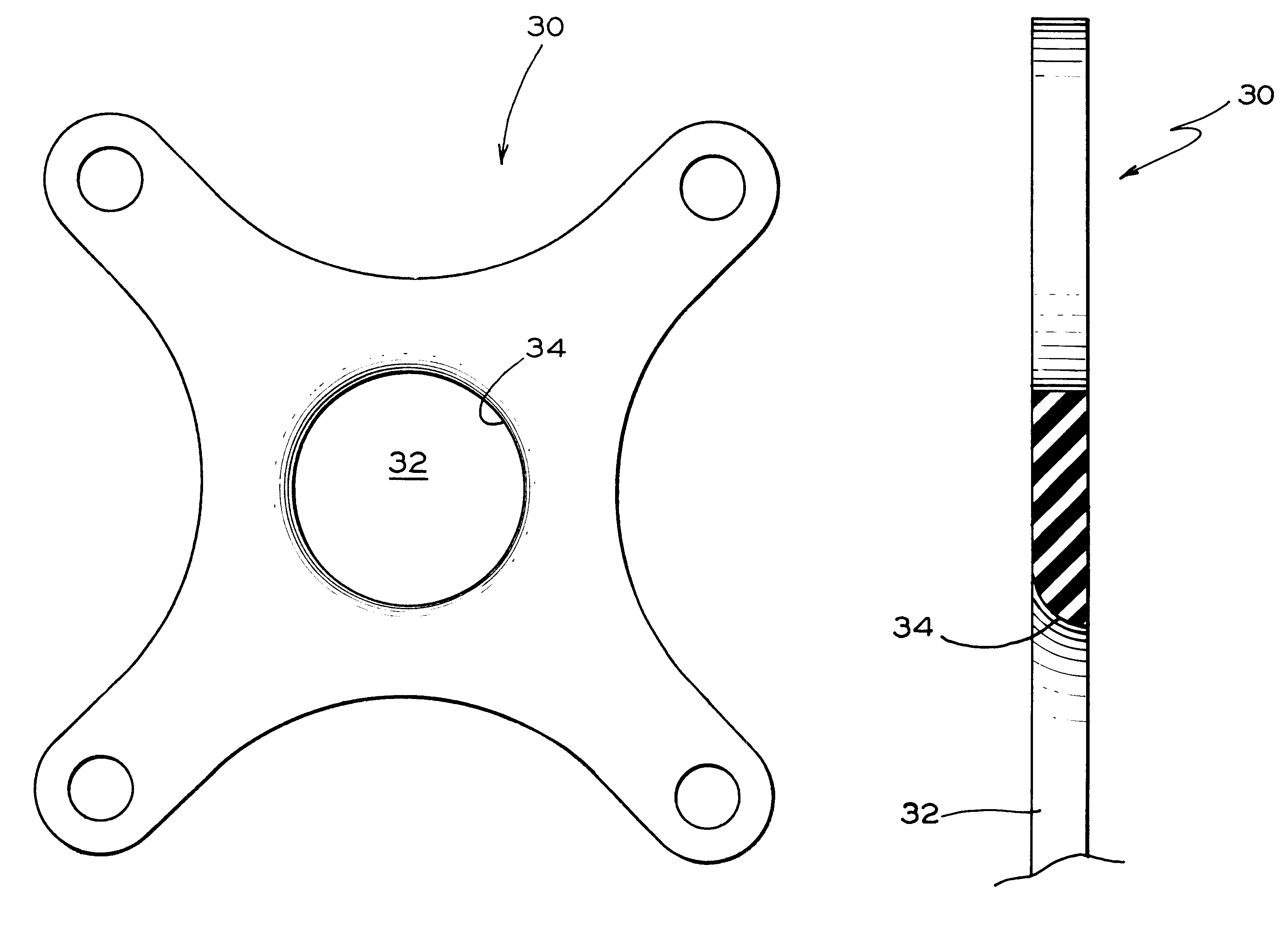
FIG. 3 is a plan view of the gasket of the invention illustrated in FIG. 2.

FIG. 4 is a plan view of a rectangular flange and the presently preferred gasket of the invention.

FIG. 5 is a plan view of a rectangular flange for attachment to the flange of FIG. 4.

FIG. 6 is a side view of a pressure connection employing the flanges and gasket of FIGS. 4 and 5.

FIG. 7 is a plan view of a gasket and flange combination which accommodates six fasteners.

FIG. 8 is a plan view of a flange for attachment to the flange of FIG. 7.

FIG. 9 is a side view of the flange of FIG. 8 attached to the gasket and flange of FIG. 7.

FIG. 10 is an isometric view of a compressor system ...


PUM


Abstract

Gasket for sealing between flanges in a pressurized fluid system. A central opening is disposed within an inner periphery of the gasket, the inner periphery being curved toward the central opening. Fluid pressure on the inner periphery is reacted by hoop tension in the gasket. The outer periphery of the gasket has concave segments between fastener holes so the area of the gasket is substantially less than the area of the flanges. In this manner, the clamping pressure exerted by the flanges on the gasket is increased.

Description

The present invention relates, in general, to fluid sealing means for pressurized fluid systems and, more particularly, to gaskets for locomotive air compressors.The compressors employed in airbrake systems used in locomotives generally have air pressure connections having rectangular flanges with gaskets clamped therebetween. A prior art flange and gasket as employed in a locomotive air compressor is shown in FIG. 1. The flange 10 includes a port 11 for fluid communication with an air conduit (not shown). Flange 10 has a plurality of holes 14 to accommodate bolts for attaching flange 10 to a similar flange (not shown) which receives the compressed air. The prior art gasket 12 is compressed between flange 10 and a second flange (not shown) by tension in the bolts to prevent air loss between the flanges. A plurality of holes 15 are provided for the bolts. The air pressure in port 11 presses outward on inner edge 16 of gasket 12. This pressure is sufficient to cause tensile stresses a...

Claims


Application Information

Patent Timeline
Patent Type & Authority Patents(United States)
IPC IPC(8): F16J15/06F16L23/00F16L23/22F16J15/10
CPCF16J15/06F16J15/106F16L23/22
Inventor SHAFFER, RONALD J.
Owner WESTINGHOUSE AIR BRAKE CO
Why Eureka
Try Eureka