Light sampling devices and projector system including same

Inactive Publication Date: 2002-11-19
COMVIEW GRAPHICS
View PDF5 Cites 9 Cited by
  • Summary
  • Abstract
  • Description
  • Claims
  • Application Information

AI Technical Summary

Benefits of technology

An object of the present invention is to provide a light sampling device which may be applied to an optical apparatus, such as an image projector, in a relatively convenient manner and at a relatively low cost.
Another object of the invention is to provide such a light sampling device which minimizes the interference with the projected image or other normal use of the light emanating from the light source.
This embodiment of the invention provides a number of advantages. Thus, since the optical fiber extends parallel to the reflector, the light sampling device can be installed very conveniently and compactly on the image projector. In addition, the slit in the reflecting face can be much smaller than the cross-sectional area of the optical fiber, thereby minimizing the interference produced by the light sampling device to the viewed image.

Problems solved by technology

Display systems based on a single image generator are limited in the number of pixels they can display (currently the limit is approximately one million), and in their brightness (the amount of light emitted from a unit image area).
In general, light sampling devices create disturbances to the image, or other form of light, emanating from the light source.
If the light sampling device is located in a light projector between the light source and the screen, the disturbances are mostly in the form of a shadow; and if the light sampling device is between the viewer and the screen, the disturbance is usually in the form of an obstruction.
If a light sampling devices has to be removed when the image is displayed or the light emanating from the light source is otherwise processed, the light sampling procedure would be considerably complicated, and the cost would be considerably increased.

Method used


Image

  • Light sampling devices and projector system including same
  • Light sampling devices and projector system including same
  • Light sampling devices and projector system including same

Examples


Embodiment Construction

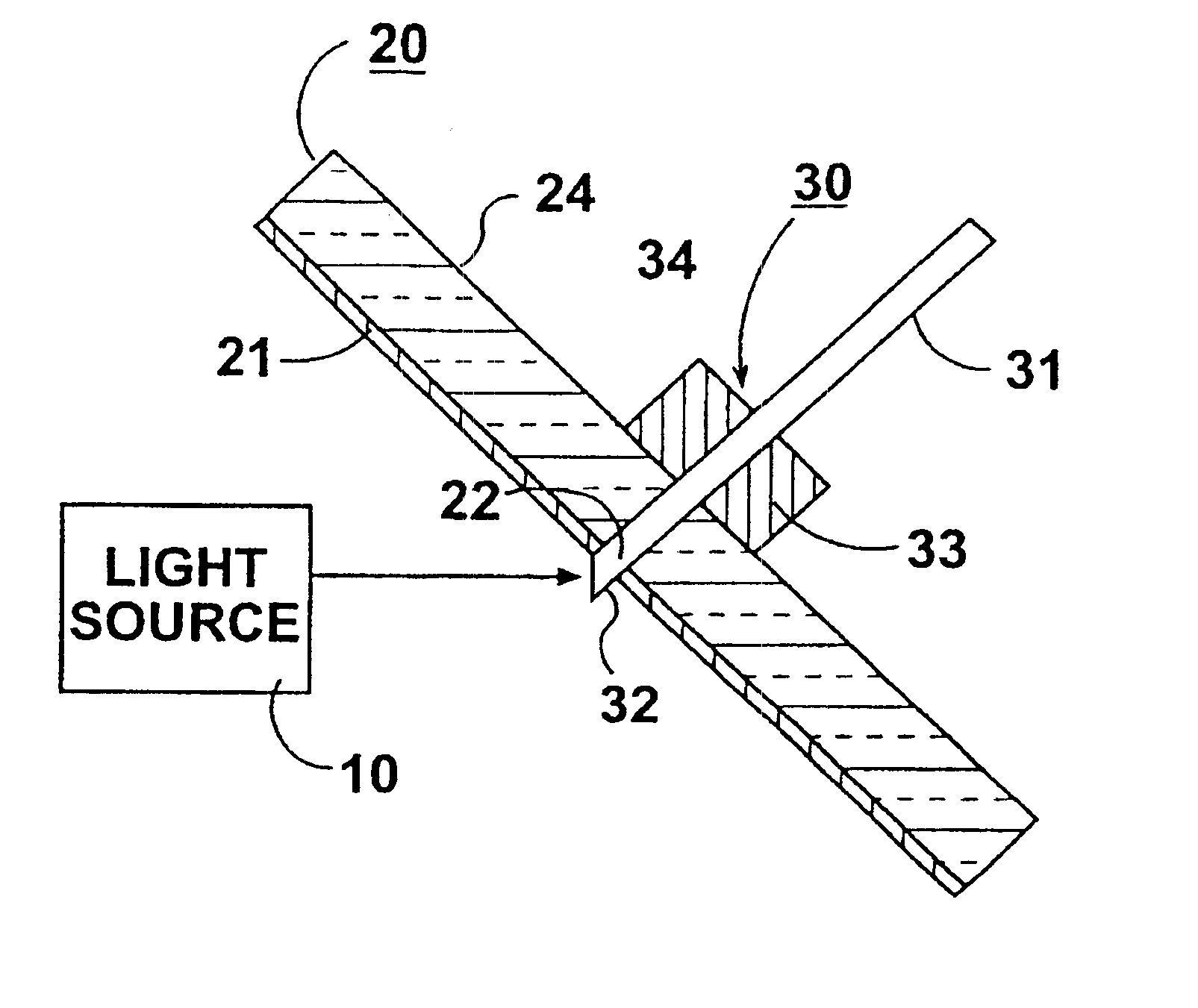
FIG. 1 illustrates one form of sampling device, namely feed-through device, constructed in accordance with the present invention. The sampling device illustrated in FIG. 1 is for use in apparatus which includes a light source 10 directed towards a reflector, generally designated 20. A sampling device, generally designated 30, is located on the side of the reflector opposite to that of the light source 10 so as not to interfere with the light emanating from the light source and directed towards the reflector.

The side OF reflector 20 facing light source 10 has a reflecting face 21 for reflecting the light emanating from the light source. Reflecting face 21 has a small interruption 22 therein, with which the sampling device 30 is aligned for extracting a sample of the light received on the reflecting face 21.

In the embodiment illustrated in FIG. 1, the interruption 22 in the reflecting face 21 is in the form of a small hole extending completely through the reflector 20 from its reflect...


PUM


Abstract

Optical apparatus includes a source light a reflector having a reflecting face on one side facing the source of light to receive light therefrom, a small interruption in the reflecting face, and a sampling device located on the opposite side of the reflector aligned with the small interruption for extracting a sample of the light received by the reflecting face.

Description

FIELD AND BACKGROUND OF THE INVENTIONThe present invention relates to light sampling devices for producing a sample of light from an optical device, e.g., for control or other processing purposes. The invention is especially useful in an image projector system including a plurality of image projectors, wherein the light samples produced by each projector are used for controlling the image projectors, e.g., to compensate for variations in color composition, light intensity, etc. The invention is therefore described below with respect to this application, but it will be appreciated that the invention could also be used in other applications where it's desired to take samples of light from an optical device for other control or processing purposes.Many types of optical devices contain mirrors to manipulate light beams or other light source. In contrast to other common optical elements such as lenses, mirrors generally confine the light to the reflecting side only. This provides a relat...

Claims


Application Information

Patent Timeline
IPC IPC(8): G02B6/42G02B27/18G03B21/00G03B21/28
CPCG02B6/4298G02B6/4202H04N5/74
Inventor WEISSMAN, YITZHAKDANKNER, YAIRALONI, MEIR
Owner COMVIEW GRAPHICS
Why Eureka
Try Eureka