Electric motor

a technology of electric motors and stators, applied in the direction of dynamo-electric machines, electrical apparatus, magnetic circuit shapes/forms/construction, etc., can solve the problems of winding fitting problems and achieve optimal alignment, so as to reduce production costs and simplify the effect of production

Inactive Publication Date: 2002-11-19
SIEMENS AG
View PDF15 Cites 72 Cited by
  • Summary
  • Abstract
  • Description
  • Claims
  • Application Information

AI Technical Summary

Benefits of technology

On this basis, it is an object of the invention to provide a structural configuration of a laminated core for a stator of an electric motor, by wh

Problems solved by technology

It is difficult in this way to achieve an optimum alignment of the sheet-metal laminates for providing an acceptable mutual angular positioning, without i

Method used


Image

  • Electric motor
  • Electric motor
  • Electric motor

Examples


Embodiment Construction

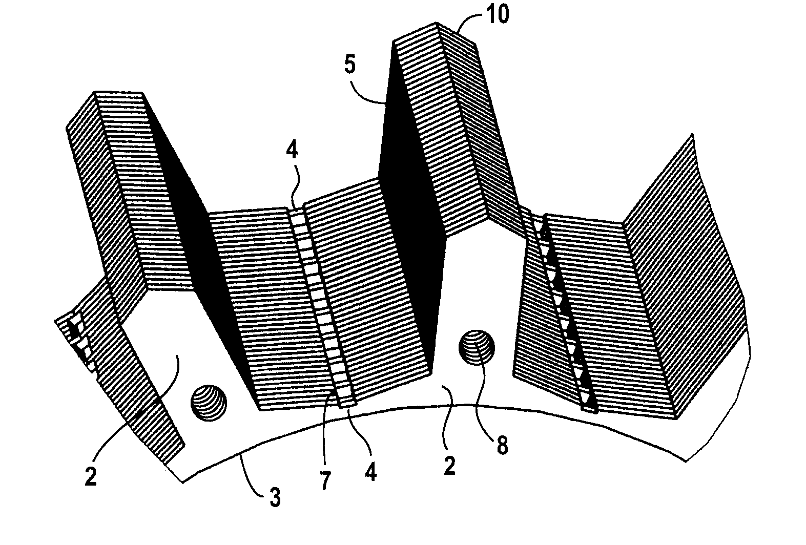
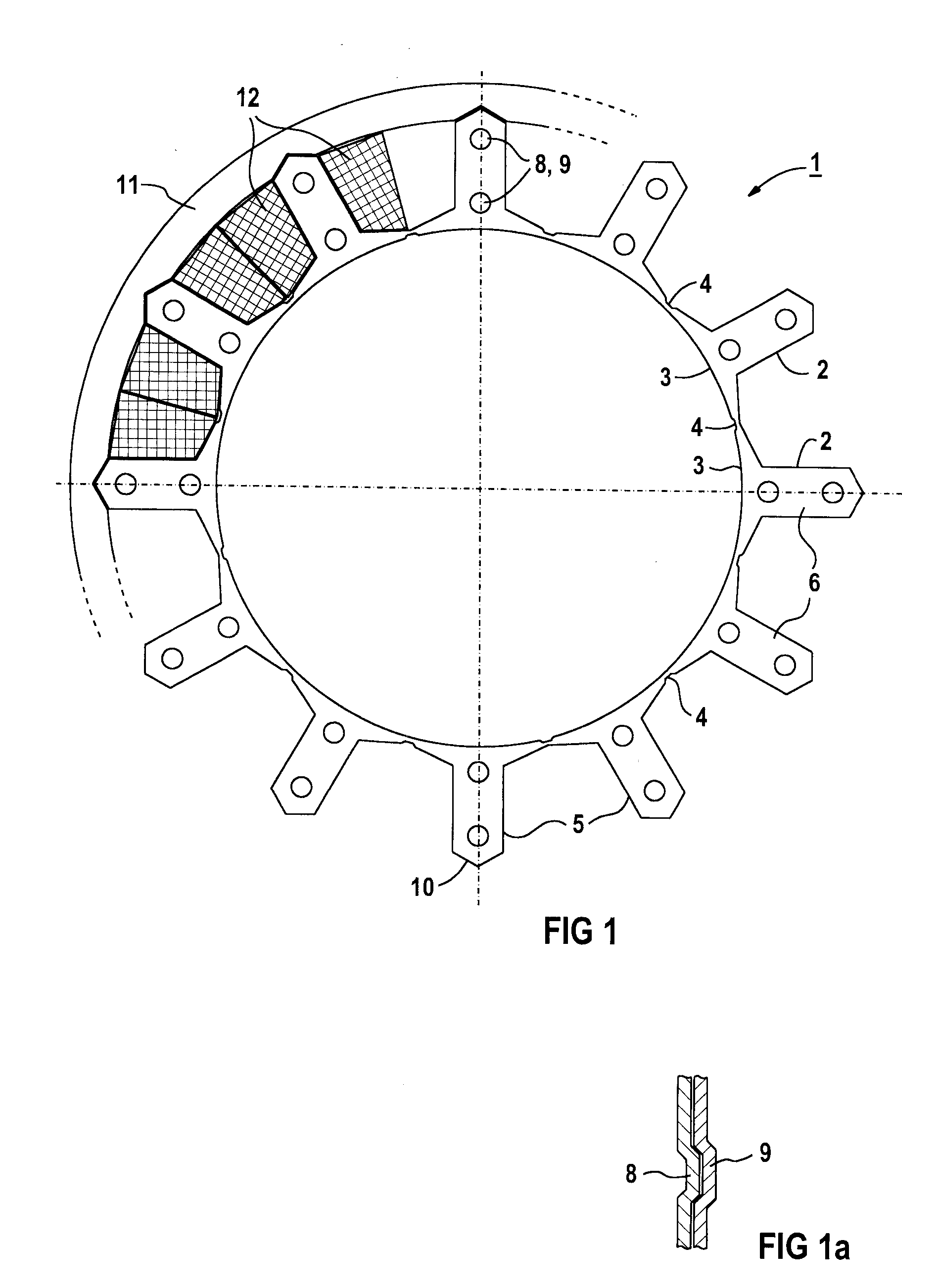
FIG. 1 shows a cross section of a symmetrical star-shaped laminated core 1 of a stator. A sheet-metal laminate 6 has poles 2 which are arranged in the shape of a star and connected at their pole shoes 3 in the circumferential direction by webs 4 and thereby terminate with the pole shoes 3 flush with respect to a side facing the rotor. It is also conceivable to arrange the webs 4 radially further outward, so that slot opening extensions face the rotor. Also, the webs are made of a material which, preferably, corresponds to the material of the pole shoes 3.

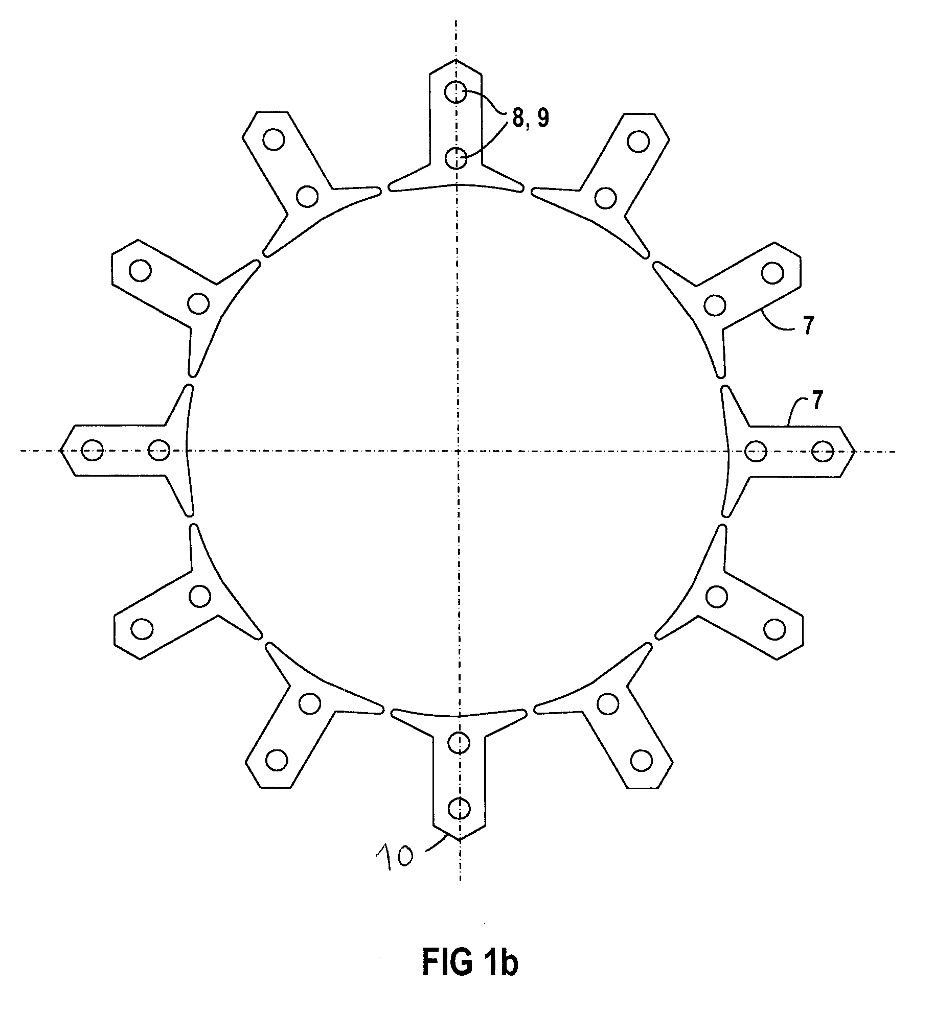
FIG. 1b depicts individual poles 7 that can also be connected by magnetic or non-magnetic clamps.

In the outward direction, pole shanks 5 are preferably formed in a roof-shaped form 10, to thereby permit and facilitate a process of heat shrinkage into a magnetic yoke, as indicated schematically in FIG. 1 by reference numeral 11 and thereby prevent twisting of the star-shaped laminated core 1 of the stator. For shrink or press fits, t...


PUM


Abstract

A method of producing a laminated core of a stator of an electric motor, includes at least one laminated core of a stator formed by stacked sheet-metal laminates, which have mechanical individual poles and of poles connected in the circumferential direction of the stator, at least one pole shank and at least one pole shoe facing a rotor. The sheet-metal laminates are configured with indentations and protrusions and, as a result, the sheet-metal laminates form the laminated core of the stator by interengagement of the indentations and protrusions. The mechanical poles of the laminated core of the stator have windings, and webs are provided between the poles to connect the connected mechanical poles in the circumferential direction. The axial set-up of the sheet-metal laminates of the laminated core of the stator has a predeterminable alternating succession of poles with a connecting web and poles without a connecting web.

Description

BACKGROUND OF THE INVENTIONThe invention relates to a laminated core of a stator of an electric motor and a method of producing it.Laminated iron cores serve for guiding the magnetic field.German Utility Model 18 82 073 discloses a laminated actuating magnet, having sheet-metal laminates provided on one side with preferably circular indentations in such a way that protrusions are formed on its opposite side and the sheet-metal laminates can be fitted together by interengagement of their indentations and protrusions to form a laminated core for the actuating magnet.It is difficult in this way to achieve an optimum alignment of the sheet-metal laminates for providing an acceptable mutual angular positioning, without impairing the magnetic properties and consequently the operating behavior of the electric motor. Furthermore, this causes problems when fitting the windings.SUMMARY OF THE INVENTIONOn this basis, it is an object of the invention to provide a structural configuration of a l...

Claims


Application Information

Patent Timeline
IPC IPC(8): H02K1/14H02K15/06H02K15/00H02K15/02H02K15/12H02K1/18
CPCH02K1/148H02K15/022H02K15/06H02K15/12H02K2201/09
Inventor PAWELLEK, JURGENSCHULZ, UDOVOLLMER, ROLF
Owner SIEMENS AG
Why Eureka
Try Eureka