Mechanical walker

a technology of mechanical walking and walker, which is applied in the direction of children's carriage/perambulator, hand cart accessories, vehicles, etc., can solve the problems of effort and attention being directed toward the construction of mechanisms

Inactive Publication Date: 2002-12-10
NEU FRLIN D
View PDF4 Cites 23 Cited by
  • Summary
  • Abstract
  • Description
  • Claims
  • Application Information

AI Technical Summary

Problems solved by technology

A great deal of effort and attention has been directed toward construction of mechanisms capable of horizontal movement.

Method used


Image

  • Mechanical walker
  • Mechanical walker
  • Mechanical walker

Examples


Embodiment Construction

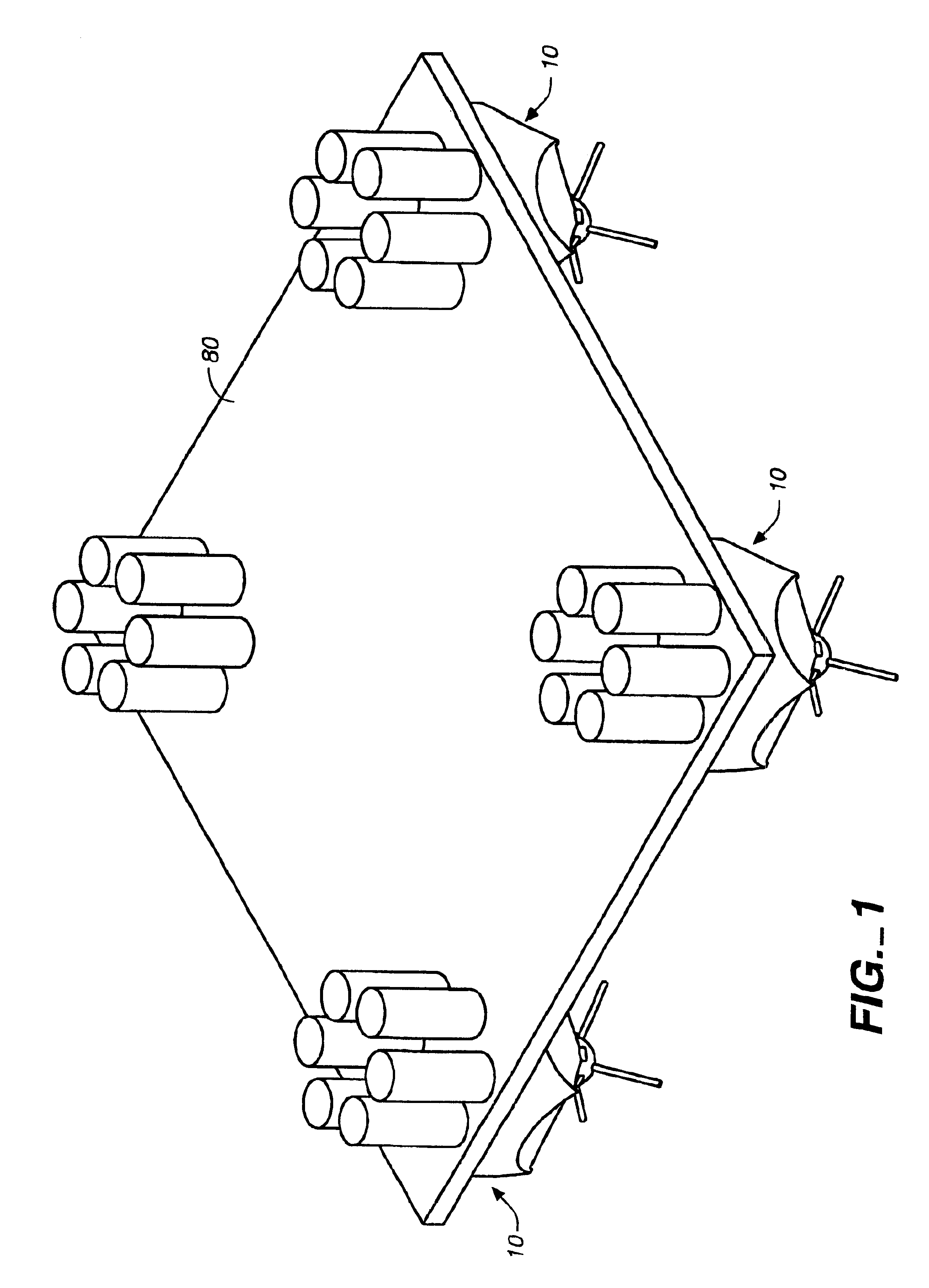
FIG. 1 is a perspective view of a mechanical walker according to the invention, comprising an assembly of four mechanical walkers supporting and joined by a conveyance platform.

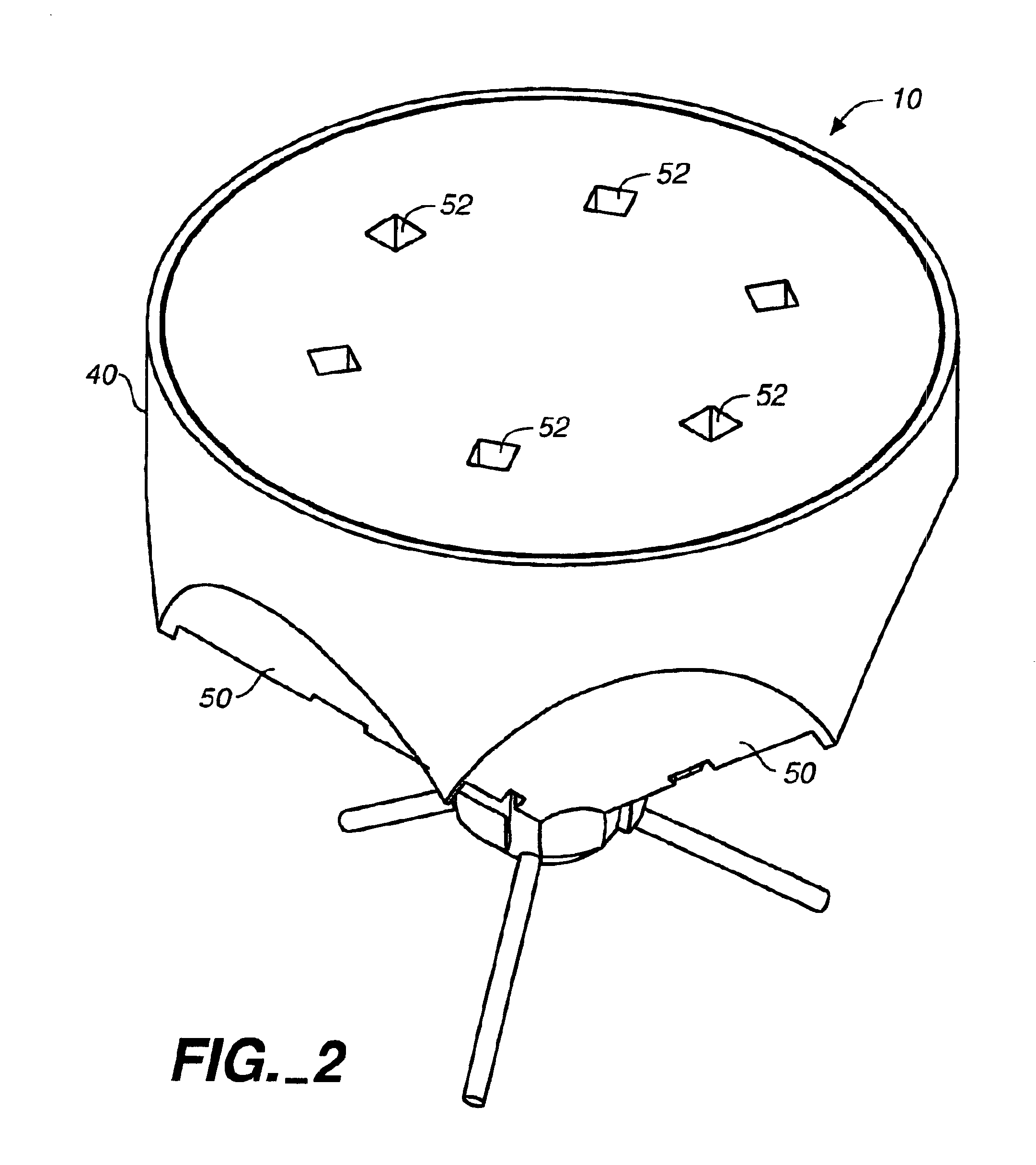
FIG. 2 is a top perspective view of a mechanical walker according to the invention.

FIG. 3 is a bottom perspective view of the mechanical walker shown in FIG. 2.

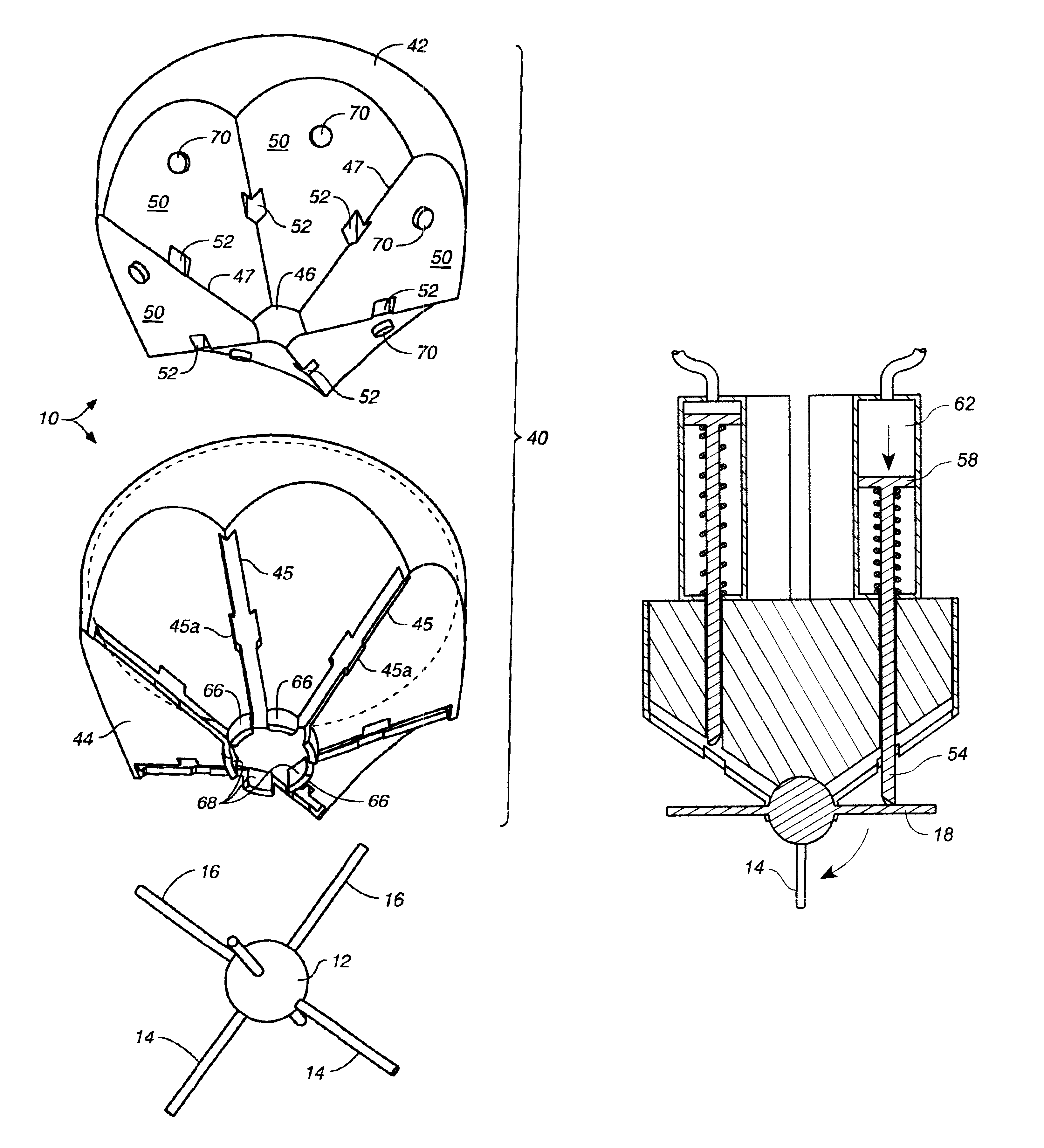
FIG. 4 is an exploded lower perspective view of the mechanical walker of FIG. 3.

FIG. 5 is a bottom plan view of the mechanical walker of FIGS. 2 and 3.

FIG. 6A is a side sectional view of the mechanical walker taken along lines 6A of FIG. 5.

FIG. 6B is a side sectional view of the mechanical walker taken along lines 6B of FIG. 5.

FIGS. 7A, 7B, and 7C are side sectional views of the mechanical walker according to the invention showing movement of the sphere and legs through one complete movement cycle.

FIG. 7D is a perspective view of an actuating rod in contact with one of the legs of a mechanical walker according to the invention.

FIG. 8 is a perspective v...


PUM


Abstract

A mechanical walker comprises six legs extending from a sphere, the legs organized in a X-Y-Z axial configuration. The sphere and legs support a bearing member. A shell holds the sphere and legs to the bearing member. Movement is accomplished by applying downward force to one of three high legs to walk it over two anchor legs moving the device in the horizontal inclination of the selected high leg. The invention is capable of horizontal movement in six directions offset from each other by sixty degrees. Preferably downward force is applied to the selected high leg using a retractable actuating rod. Slots in the shell, and a groove and prominences in a bottom portion of the actuating rod, prevent the high leg from drifting horizontally. At least three mechanical walkers can support a platform or other conveyance means.

Description

1. Field of the InventionThis invention relates to mechanical walkers, and particularly to robotic walking mechanisms having six legs of equal length organized in an X-Y-Z axial relationship extending radially from a central sphere, wherein movement over a surface is accomplished by rotation of the legs and sphere. The invention also relates to a superstructure for conveyance of items supported by a plurality of such walkers.2. Description of the Related ArtA great deal of effort and attention has been directed toward construction of mechanisms capable of horizontal movement. Myriad applications of the wheel have been designed and built, but they generally require a smooth surface especially as speeds increase. All wheel-reliant machines must incorporate a braking system to prevent movement on slanted or irregular surfaces. The National Aeronautics and Space Administration, universities, and independent research laboratories, have created sophisticated walking and movement devices w...

Claims


Application Information

Patent Timeline
Patent Type & Authority Patents(United States)
IPC IPC(8): B62D57/00B62D57/032
CPCB62D57/032
Inventor NEU, FRANKLIN D
Owner NEU FRLIN D
Why Eureka
Try Eureka