
Optical glass forming mold device

A technology for molding molds and optical glass, applied in glass molding, glass pressing, glass manufacturing equipment, etc., can solve problems such as poor practical effect and single structure, and achieve the effect of improving practicability and ensuring stability

Active Publication Date: 2022-02-08
NANTONG RUISEN OPTICAL CO LTD
View PDF9 Cites 0 Cited by
  • Summary
  • Abstract
  • Description
  • Claims
  • Application Information

AI Technical Summary

Problems solved by technology

[0004] The object of the present invention is to provide a kind of optical glass forming mold device, to solve the existing optical glass forming mold device proposed in the above-mentioned background technology is only a single structure, needs to manufacture the optical glass of different structural types by different forming mold devices, The problem of poor practical effect

Method used


Image

  • Optical glass forming mold device
  • Optical glass forming mold device
  • Optical glass forming mold device

Examples


Embodiment Construction

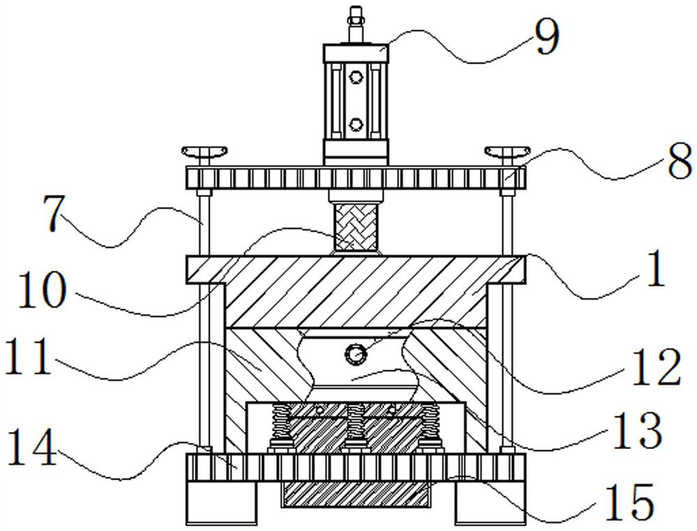
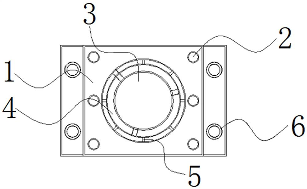
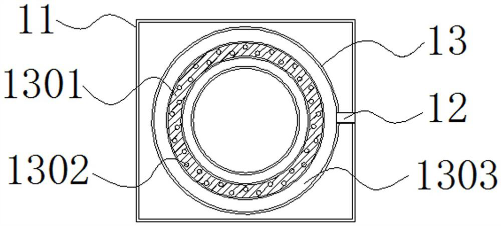
[0022] see Figure 1-5 , an optical glass forming mold device, comprising an upper mold 1, a sinking ring groove 4 and a positioning opening 5, the bottom of the upper mold 1 is fixed with a limited connecting column 2 around, and the middle part of the bottom of the upper mold 1 is provided with a template placement groove 3. The sinking ring groove 4 is opened on the outside of the formwork placement groove 3, and the positioning openings 5 ​​are distributed on the outside of the sinking ring groove 4;

[0023] The specific operation is as follows. There are multiple sets of annular positioning openings 5 ​​distributed equidistantly on the outside of the sinking ring groove 4. The positioning openings 5 ​​are all in a rectangular concave shape, which fits the structure of the mold core. The opening 5 and the mold core are positioned and buckled, and then the forming template is positioned and installed, and a variety of different types of templates are respectively snapped i...


PUM


Abstract

The invention discloses an optical glass forming mold device, and relates to the technical field of optical glass forming. The device concretely comprises an upper mold, a sinking ring groove and positioning open holes. The periphery of the bottom end of the upper mold is fixedly provided with limiting connecting columns, the middle of the bottom end of the upper mold is provided with a mold plate containing groove, the sinking ring groove is formed in the outer side of the mold plate containing groove, and the positioning open holes are distributed in the outer side of the sinking ring groove. The optical glass forming mold device is provided with the positioning open holes, the multiple sets of positioning open holes which are annularly distributed at equal intervals are formed in the outer side of the sinking annular groove, the positioning open holes are each of a rectangular inwards-concave structure matched with the mold core, when the optical glass forming mold device is used, positioning and buckling are conducted through the multiple sets of positioning open holes and the mold core, and then the forming mold plate is positioned and installed; different types of mold plates are buckled in the mold plate containing groove formed in the middle of the sinking ring groove, and then optical glass with different structural requirements is machined, so that the mold can be suitable for forming and manufacturing of multiple different optical glass, and the practicability of the mold is improved.

Description

technical field [0001] The invention relates to the technical field of optical glass molding, in particular to an optical glass molding mold device. Background technique [0002] Optical glass refers to glass that can change the propagation direction of light and change the relative spectral distribution of ultraviolet, visible or infrared light. Optical glass in a narrow sense refers to colorless optical glass; optical glass in a broad sense also includes colored optical glass, laser glass , quartz optical glass, anti-radiation glass, ultraviolet infrared optical glass, fiber optic glass, acousto-optic glass, magneto-optic glass and photochromic glass. Optical glass can be used to manufacture lenses, prisms, mirrors and windows in optical instruments. Components made of optical glass are key components in optical instruments, and they need to be shaped by mold devices during the molding process of optical glass. [0003] The existing optical glass forming mold device has ...

Claims


Application Information

Patent Timeline
Patent Type & Authority Applications(China)
IPC IPC(8): C03B11/06C03B11/12C03B11/16
CPCC03B11/06C03B11/12C03B11/16
Inventor 王森林杨爱梅
Owner NANTONG RUISEN OPTICAL CO LTD
Learn More