
Sponge cutting device with vertical wire knife

A sponge cutting and vertical knife technology, which is applied in metal processing and other directions, can solve the problems of high temperature of the cutter, material damage, large contact area between the cutter and the sponge, etc., to reduce roughness, reduce loss, and avoid high temperature damage sponge effect

Inactive Publication Date: 2021-07-27
南通智谷数控机械有限公司
View PDF7 Cites 0 Cited by
  • Summary
  • Abstract
  • Description
  • Claims
  • Application Information

AI Technical Summary

Problems solved by technology

[0003] The object of the present invention is to provide a kind of sponge cutting device with thread cutter, to solve the above-mentioned background technology, existing sponge cutting device adopts cutter to cut sponge mostly, and the contact area of ​​cutter and sponge is large, and it takes a long time After use, the surface of the cutter is prone to high temperature, which will adversely affect the cutting surface of the sponge, and when the sponge is being cut, it is not convenient for the user to locate the position of the sponge, which may cause the sponge to shift during cutting, resulting in material damage.

Method used


Image

  • Sponge cutting device with vertical wire knife
  • Sponge cutting device with vertical wire knife
  • Sponge cutting device with vertical wire knife

Examples


Embodiment 1

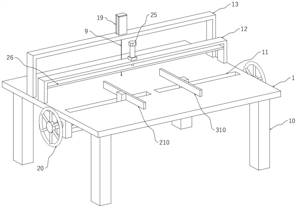
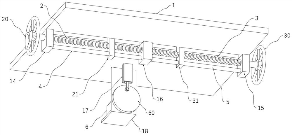
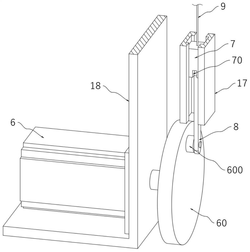
[0029]The sponge cutting device with thread cutter of the present invention comprises a workbench 1, the bottom of the workbench 1 and the positions near the four corners are all provided with supporting legs 10, the surface of the workbench 1 and the positions near the front side are provided with Symmetrically distributed bar-shaped chute 11, the edges on both sides of the bottom of the workbench 1 and near the front side are provided with symmetrically distributed first fixed projections 14 and second fixed projections 15, the bottom of the workbench 1 is located at the first The position between a fixed projection 14 and the second fixed projection 15 is provided with the third fixed projection 16, and the first screw rod 2 is connected with the rotation between the first fixed projection 14 and the third fixed projection 16. The outer wall of the screw 2 is threaded with a first moving block 21, the position of the first moving block 21 is adjusted by the first screw 2, an...

Embodiment 2

[0031] The sponge cutting device with thread cutter of the present invention comprises a workbench 1, the bottom of the workbench 1 and the positions near the four corners are all provided with supporting legs 10, the surface of the workbench 1 and the positions near the front side are provided with Symmetrically distributed bar-shaped chute 11, the edges on both sides of the bottom of the workbench 1 and near the front side are provided with symmetrically distributed first fixed projections 14 and second fixed projections 15, the bottom of the workbench 1 is located at the first The position between a fixed projection 14 and the second fixed projection 15 is provided with the third fixed projection 16, and the first screw rod 2 is connected with the rotation between the first fixed projection 14 and the third fixed projection 16. The outer wall of the screw 2 is threaded with a first moving block 21, the position of the first moving block 21 is adjusted by the first screw 2, a...

Embodiment 3

[0037] The sponge cutting device with thread cutter of the present invention comprises a workbench 1, the bottom of the workbench 1 and the positions near the four corners are all provided with supporting legs 10, the surface of the workbench 1 and the positions near the front side are provided with Symmetrically distributed bar-shaped chute 11, the edges on both sides of the bottom of the workbench 1 and near the front side are provided with symmetrically distributed first fixed projections 14 and second fixed projections 15, the bottom of the workbench 1 is located at the first The position between a fixed projection 14 and the second fixed projection 15 is provided with the third fixed projection 16, and the first screw rod 2 is connected with the rotation between the first fixed projection 14 and the third fixed projection 16. The outer wall of the screw 2 is threaded with a first moving block 21, the position of the first moving block 21 is adjusted by the first screw 2, a...


PUM


Abstract

The invention relates to the technical field of cutting devices, in particular to a sponge cutting device with a vertical wire knife. The sponge cutting device with the vertical wire knife comprises a workbench; a second U-shaped support is arranged in the position, close to the rear side, on the surface of the workbench; second U-shaped slide rails are symmetrically distributed in the middle of the top of the second U-shaped support; a second slide block is connected between the two second U-shaped slide rails in a sliding mode; a wire knife is arranged in the middle of the bottom of the second sliding block; an L-shaped support is arranged in the position, close to the rear side, at the bottom of the workbench; a servo motor is arranged at the top of a horizontal plate of the L-shaped support; and the end part of an output shaft of the servo motor penetrates through the side face of a vertical plate of the L-shaped support and is connected with a rotating wheel. According to the sponge cutting device with the vertical wire knife, the rotating wheel is driven by the servo motor to rotate, so that the first sliding block is driven by a connecting rod to move in a reciprocating mode, and the wire knife moves at a high speed to cut sponge; and as the contact surface between the wire knife and the sponge is small, the situation that the sponge is damaged by high temperature due to large-area contact with the sponge in common cutting can be avoided.

Description

technical field [0001] The invention relates to the technical field of cutting devices, in particular to a sponge cutting device with a thread cutter. Background technique [0002] Sponge is a porous material with good water absorption and can be used to clean items. Commonly used sponges are made of wood cellulose fibers or foamed plastic polymers. During the production and processing of sponges, different sponges need to be processed. Size cutting, most of the existing sponge cutting devices use a cutter to cut the sponge. The contact area between the cutter and the sponge is large, and the surface of the cutter is prone to high temperature after long-term use, which will adversely affect the cutting surface of the sponge. When the sponge is being cut, it is inconvenient for the user to locate the position of the sponge, which may cause the sponge to shift during cutting and cause material damage. In view of this, we propose a sponge cutting device with a thread cutter. ...

Claims


Application Information

Patent Timeline
Patent Type & Authority Applications(China)
IPC IPC(8): B26D1/547B26D7/04B26D7/22
CPCB26D1/547B26D7/04B26D7/22
Inventor 佘露根袁彬彬汤伟哲石海龙任海军
Owner 南通智谷数控机械有限公司
Learn More