Vehicle air conditioner having air suction port for each seat

a technology for air conditioners and seats, which is applied in vehicle arrangements, vehicle heating/cooling devices, transportation and packaging, etc., can solve the problems of deteriorating independent air-conditioning control, difficulty in performing independent air-conditioning control, and insufficient air distribution to the second seat sid

Inactive Publication Date: 2002-12-10
DENSO CORP
View PDF10 Cites 97 Cited by
  • Summary
  • Abstract
  • Description
  • Claims
  • Application Information

AI Technical Summary

Benefits of technology

It is an another object of the present invention to provide a vehicle air conditioner which improves an independent air-conditioning control performance in each seat without increasing an air-blowing amount from air outlets.
According to the present invention, in a vehicle air conditioner, each of plural suction ports is provided for each of plural seats so that air inside the passenger compartment is sucked from the suction ports to be introduced into an air passage of an air conditioning duct of an air conditioning unit, and each of outlets is provided for each air-conditioning space of the seats in the passenger compartment so that air from the air passage of the air conditioning duct is blown toward each air-conditioning space of the seats. Accordingly, a flow of conditioned air blown toward a passenger on each seat can be effectively distributed in each seat, air-conditioning operation desired by a passenger on each seat can be effectively performed. Thus, when the air conditioning unit is constructed to independently control an air state such as a suction air amount, an air-blowing amount, an air temperature and an air-flowing direction, the independent control of the air conditioning state can be effectively performed for each air conditioning space of the seats.
Preferably, a forced suction member, for forcibly sucking air inside the passenger compartment from the suction ports into the air passage of the air conditioning duct, is disposed separately from a blower of the air conditioning unit. Therefore, plural air conditioning spaces can be effectively independently provided in the seats, respectively, and independent air-conditioning control performance can be improved in each seat without increasing the air amount blown from the air outlets.
Preferably, a seat air duct, through which air from the air conditioning unit and air from the passenger compartment can be selectively introduced into each of the seats, can be provided, the seat air duct is disposed to be integrated with each of the seats, and the forced suction member is a seat blower which is disposed in the seat air duct so that air introduced into the seat air duct is blown from a seat surface. Accordingly, air sucked from the suction ports can be blown from the seat surface of each seat, while the independent air-conditioning control performance of each air conditioning space of the seats is improved.
On the other hand, the blower control unit controls the air amount sucked from the suction ports to become larger than a predetermined amount in an air outlet mode where air is mainly blown toward an upper side of each seat, and the blower control unit controls the air amount sucked from the suction ports to become smaller than the predetermined amount in an air outlet mode where air is mainly blown toward a lower side of each seat. Therefore, air conditioning feeling for a passenger in each seat can be improved.

Problems solved by technology

However, when a heat load (e.g., air amount, air temperature) at the rear right side is different from that at the rear left side, it is difficult to perform an independent air-conditioning control.
Accordingly, air cannot be sufficiently distributed to the second seat side, and an independent air-conditioning control for each seat is deteriorated.
Accordingly, consumed power for performing air-conditioning operation is increased, and air-blowing noise is increased.

Method used


Image

  • Vehicle air conditioner having air suction port for each seat
  • Vehicle air conditioner having air suction port for each seat
  • Vehicle air conditioner having air suction port for each seat

Examples


first embodiment

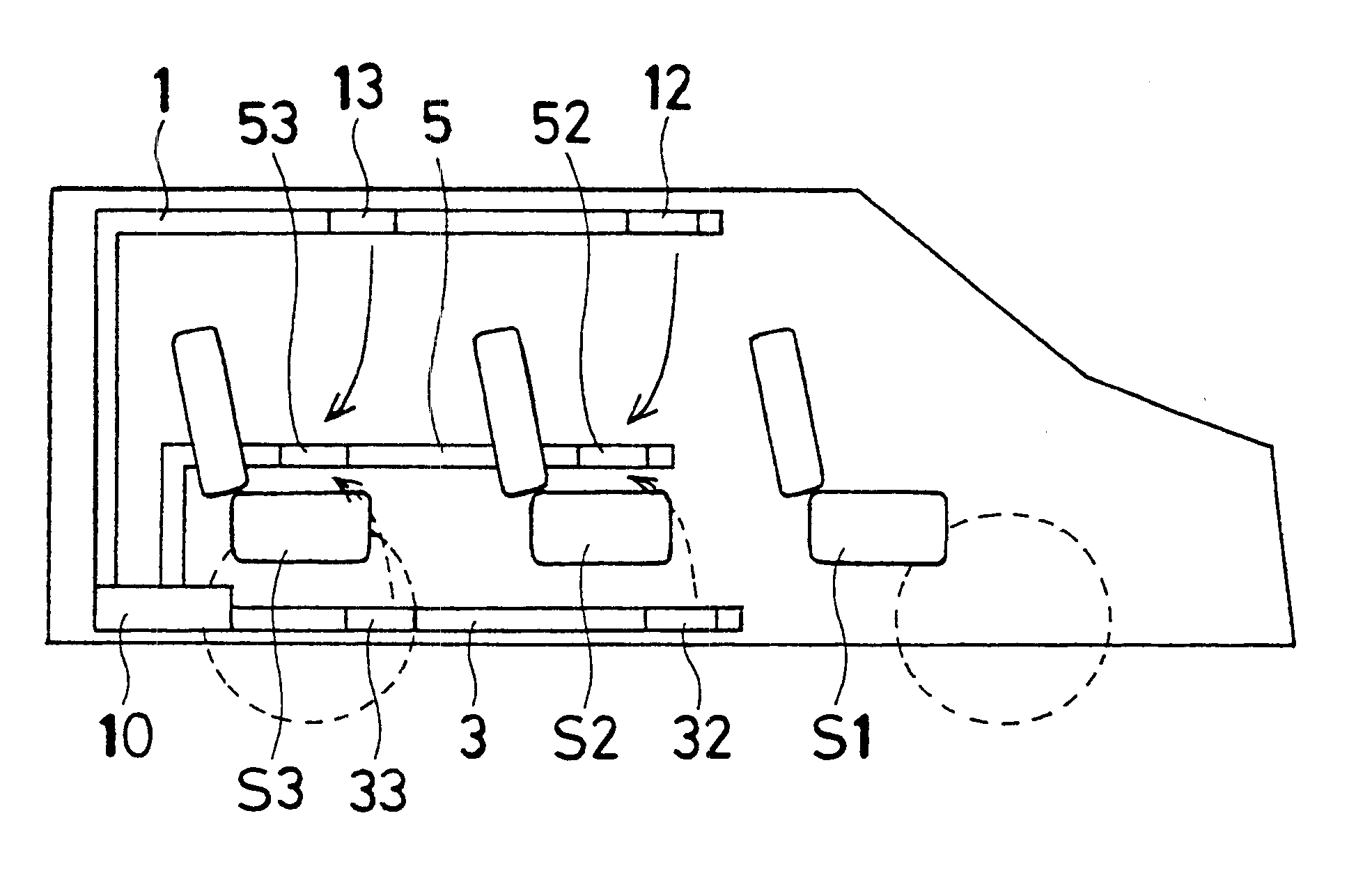
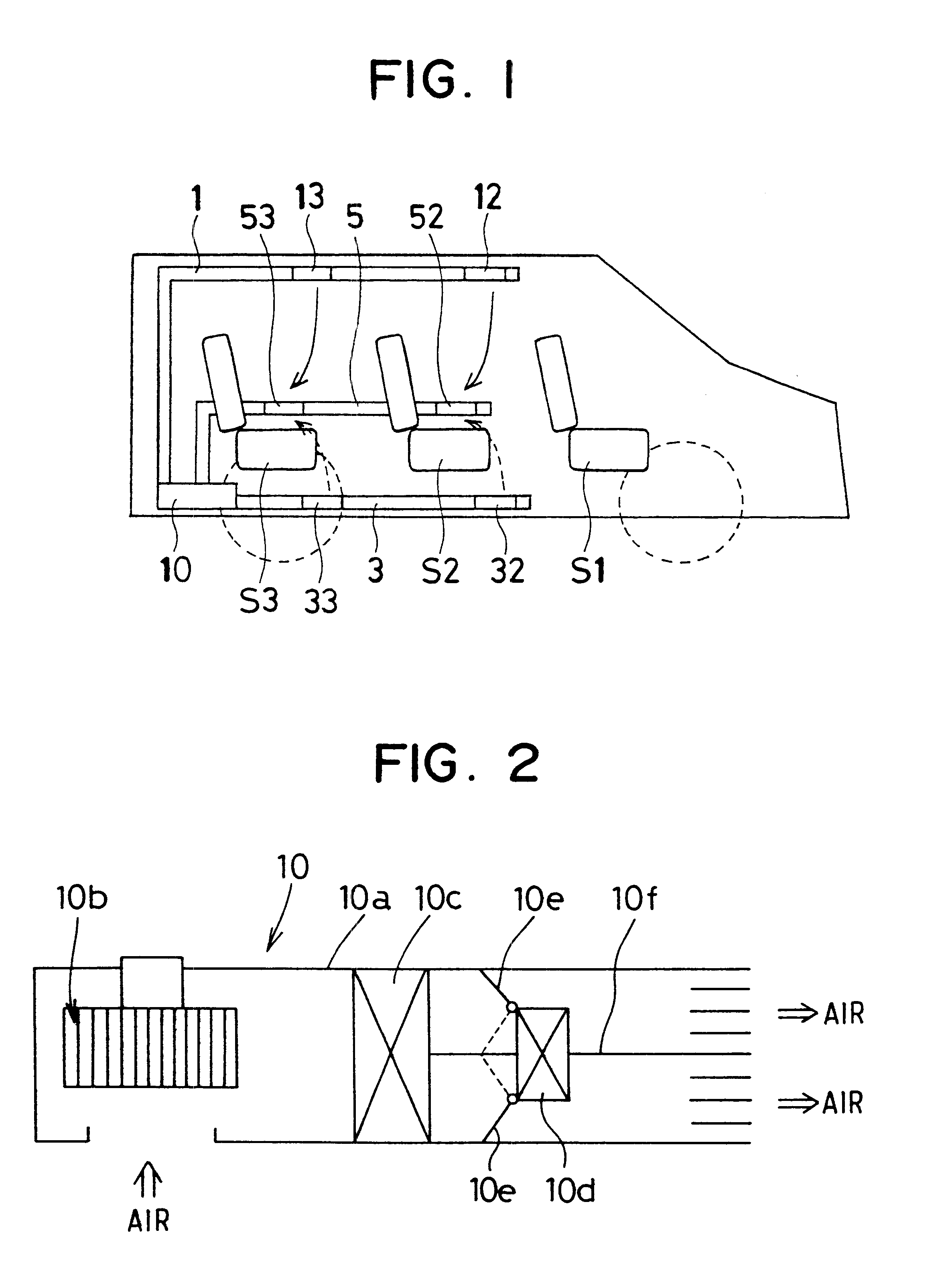
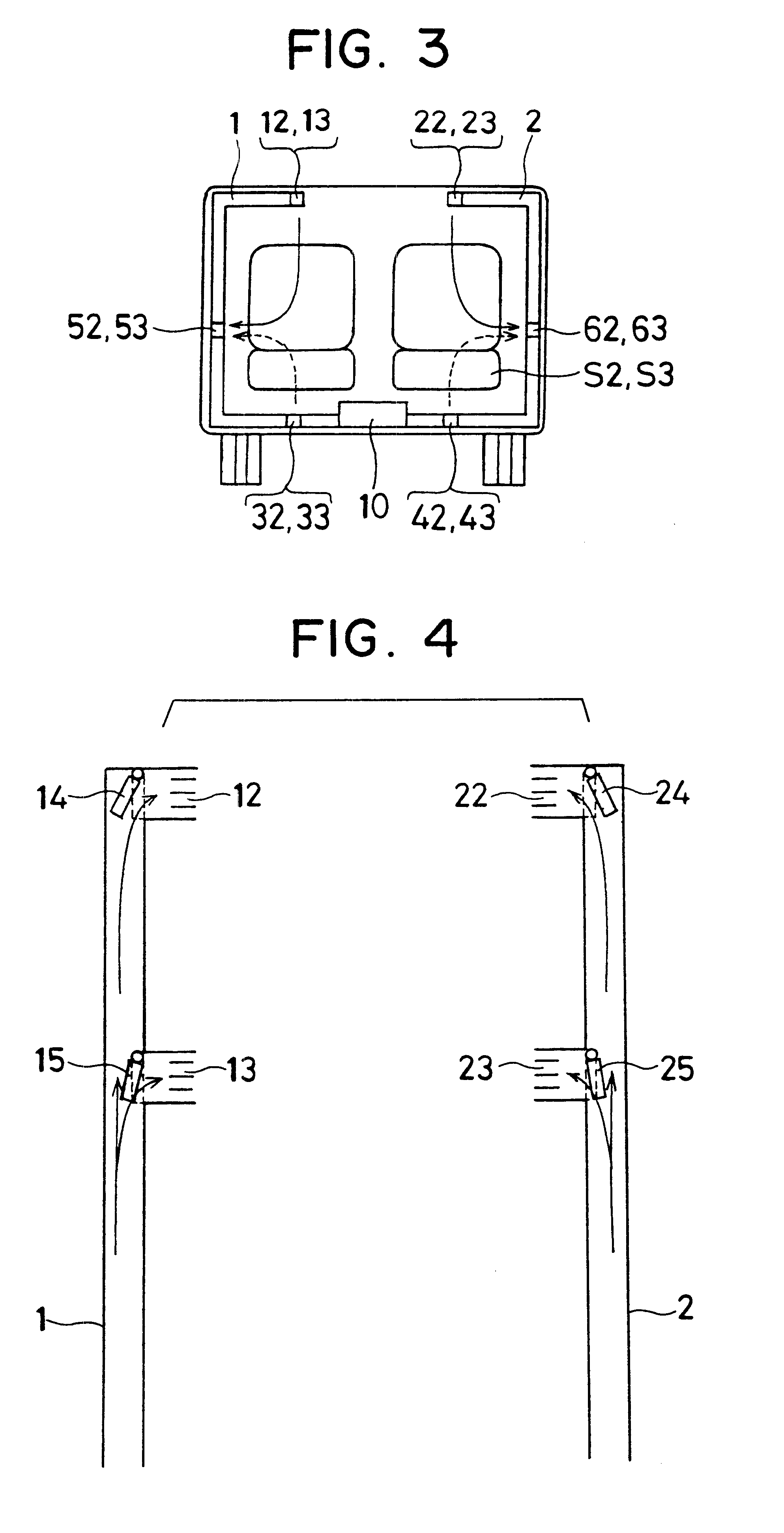
A first preferred embodiment of the present invention will be now described with reference to FIGS. 1-6. In the first embodiment, a vehicle air conditioner includes a front air conditioning unit (not shown) for performing air-conditioning operation of a passenger on a first seat (i.e., front seat) S1 at the first line within a passenger compartment, a rear air conditioning unit 10 for performing air-conditioning operation for a passenger on a second seat (i.e., rear seat) at the second line within the passenger compartment and for a passenger at a third seat (i.e., rear seat) at the third line within the passenger compartment, and a control unit for controlling components of the front air conditioning unit and the rear air conditioning unit 10.

The front air conditioning unit includes a front air duct defining an air passage, a front blower generating an air flow in the air passage toward the passenger compartment, and a front control unit which independently controls air-conditionin...

second embodiment

A second preferred embodiment of the present invention will be now described with reference to FIG. 7. FIG. 7 shows a main part of the rear air conditioning unit 10 when being viewed from a vehicle rear side. In the second embodiment, as shown in FIG. 7, a single warm air duct 7 for introducing warm air toward of the left side of the passenger on the seat S2, S3 is disposed at an approximate center in the vehicle width direction to extent to the vehicle front side from the rear air conditioning unit 10, and an a warm air passage within the warm air duct 7 is separated into two parts for right and left seat sides in each rear seat S2, S3. As shown in FIG. 7, warm air outlets 72a, 72b, 73a, 73b are provided in the warm air duct 7 at positions corresponding to the foot spaces of each second and third seats S2, S3. Therefore, warm air from the warm air outlets 72a, 72b mainly flows toward the suction ports 52, 53, respectively, and warm air from the warm air outlets 73a, 73b mainly flow...

fourth embodiment

A fourth preferred embodiment of the present invention will be now described with reference to FIGS. 9-13. A vehicle air conditioner of the fourth embodiment includes a front air conditioning unit (not shown) for performing air-conditioning operation of a passenger on a first seat (i.e., front seat) at the first line within the passenger compartment, a rear air conditioning unit 10 for performing air-conditioning operation of a passenger on a second seat (i.e., rear seat) at the second line within the passenger compartment and a passenger on a third seat (i.e., rear seat) at the third line within the passenger compartment, and a control unit (ECU) for controlling components of the front air conditioning unit and the rear air conditioning unit 10.

The front air conditioning unit includes a front air duct defining an air passage, a front blower generating an air flow in the air passage toward the passenger compartment, and a front control unit which independently controls air-condition...


PUM


Abstract

In a vehicle air conditioner, each of cool air outlets is provided at an upper side of each seat at second and third seat lines from a most front seat so that cool air from an air conditioning unit is blown from the cool air outlets toward upper sides of the seats, respectively, and each of warm air outlets is provided at a lower side of each seat at the second and third seat lines so that warm air from the air conditioning unit is blown from the warm air outlets toward lower sides of the seats, respectively. In addition, each of suction ports is provided for each corresponding seat at the second and third seat lines so that air inside a passenger compartment is sucked from the suction ports to be returned to the air conditioning unit.

Description

This application is related to Japanese Patent Applications No. 2000-96307 filed on Mar. 31, 2000, and No. 2000-317080 filed on Oct. 17, 2000.1. Field of the InventionThe present invention relates to a vehicle air conditioner having inside air suction ports each of which is provided for each seat in a passenger compartment. More particularly, a forced suction blower is disposed at a downstream side of the inside air suction ports to forcibly suck inside air of the passenger compartment from the inside air suction ports in the vehicle air conditioner.2. Description of Related ArtIn a conventional vehicle air conditioner described in JP-A-10-6744, a rear air conditioning unit for heating or cooling a rear seat side within a passenger compartment is provided. Further, a suction port, from which air inside the passenger compartment is sucked, is provided in one of right and left rear side panels, and an air outlet, from which conditioned air of the rear air conditioning unit is blown to...

Claims


Application Information

Patent Timeline
Patent Type & Authority Patents(United States)
IPC IPC(8): B60H1/00B60H1/24B60N2/56
CPCB60H1/00007B60H1/00207B60H1/247B60N2/5628B60N2/5657B60H2001/00185
Inventor YOSHINORI, TAKESHISAKAI, KOUJIAOKI, SHINJIKAJINO, YUICHI
Owner DENSO CORP
Why Eureka
Try Eureka