Pyro/piezo sensor

a technology of pyro/piezo sensor and piezo sensor, which is applied in the field of electromechanical sensors, can solve the problems of false positives and the difficulty of resorting to signal processing approaches

Inactive Publication Date: 2002-12-10
DYMEDIX
View PDF4 Cites 40 Cited by
  • Summary
  • Abstract
  • Description
  • Claims
  • Application Information

AI Technical Summary

Problems solved by technology

These facts result in a difficulty in preventing the thermal component of the transducer from crossing over into the sound channel, often leading to the occurrence of false positives when both sound signals and temperature signals are being simultaneously monitored.
The problem thus presents itself as to how one may effectively separate the signals when the frequency components of each signal overlap.
Resorting to a signal processing approach has proven difficult.

Method used


Image

  • Pyro/piezo sensor
  • Pyro/piezo sensor
  • Pyro/piezo sensor

Examples


Embodiment Construction

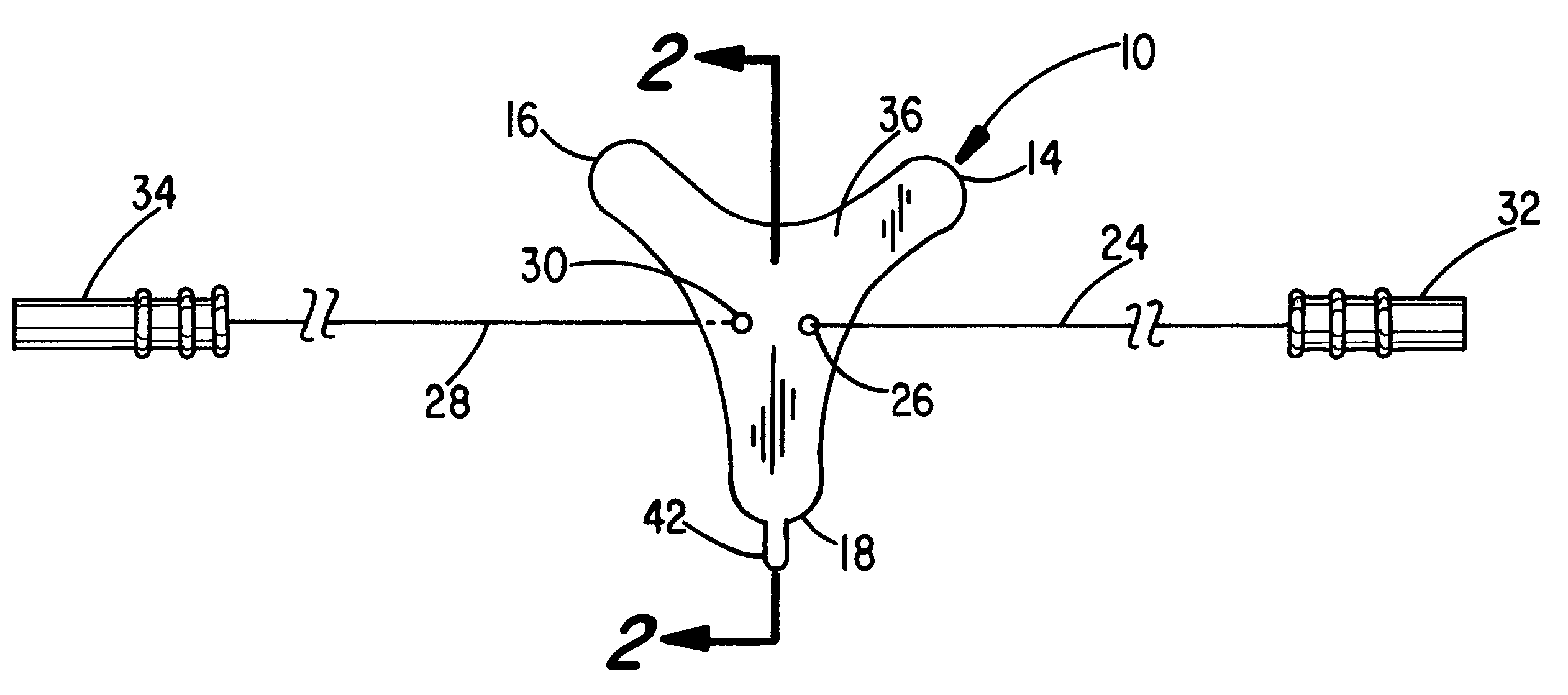
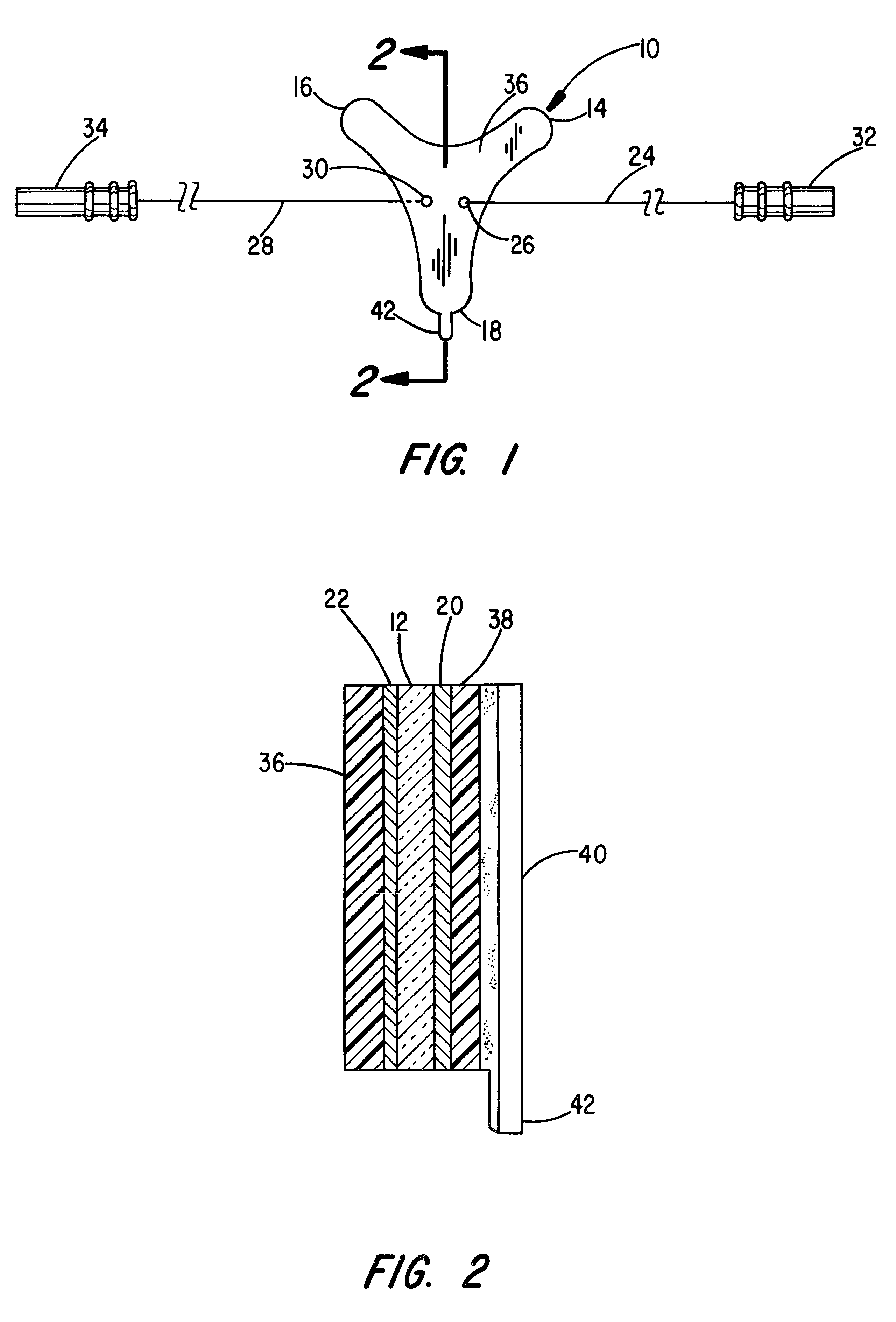
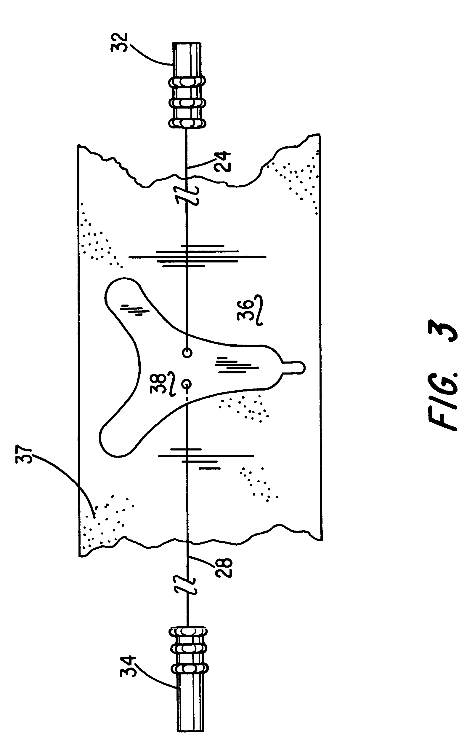
Referring to FIG. 5, there is shown an alternative embodiment of the invention designed to enhance the signal-to-noise ratio produced in the sound channel. As in the embodiment of FIG. 1, the device comprises a laminated structure including a PVDF film layer 50 having a conductive pattern, as at 52, on the opposed major surfaces thereof Without limitation, the conductive pattern may be applied as a carbon based ink or metal deposition.

The shape of the film layer 50 is bilaterally symmetrical about a longitudinal axis and includes a generally rectangular center section 54 having obliquely extending rounded arms 56 and 58 projecting from adjacent upper corner portions thereof and laterally extending legs 60 and 62 at the base of the rectangular mid-section 54. Extending normal to the upper edge of the central portion midway between the obliquely extending arms 56 and 58 is a rectangular tab segment 64.

A foam layer 66, corresponding in shape to the film layer 50, is adhesively bonded t...


PUM


Abstract

A combination thermal and vibration sensor for use in sleep monitoring equipment comprises a thin film of a plastic exhibiting both pyroelectric and piezoelectric properties. By providing a layer of foam material totally covering one major surface of the plastic film layer, it is found that the thermal mass of the sensor is changed to the point where the pyroelectric signal can more readily be isolated from the piezoelectric signal using conventional signal processing techniques.

Description

1. Field of the InventionThis invention relates generally to electronic sensors for monitoring both temperature changes and sound using a single transducer, and more particularly to the construction of such sensors that more readily allows the temperature signal to be separated from the sound signal using conventional signal processing techniques (filtering).2. Discussion of the Prior ArtIn the Stasz U.S. Pat. No. 5,311,875, which is hereby incorporated by reference, there is described a system for electronically monitoring breathing patterns. The system described therein utilizes a plastic film exhibiting both pyroelectric and piezoelectric properties such as a polyvinylidene fluoride (PVDF) film. The film transducer has a conductive electrode on opposed major surfaces thereof and electrical wires connect the electrodes to an electronics module that is designed to separate the transducer output into two separate channels, one being for temperature and the other being for sound or v...

Claims


Application Information

Patent Timeline
Patent Type & Authority Patents(United States)
IPC IPC(8): A61B5/08A61B7/00
CPCA61B5/0816A61B7/003A61B2560/0252A61B2562/0204
Inventor STASZ, PETER
Owner DYMEDIX
Why Eureka
Try Eureka