Removable cable support apparatus

a technology of supporting apparatus and cable, which is applied in the direction of instruments, signs, furniture parts, etc., to achieve the effects of convenient installation and repositioning, easy observation and identification, and low manufacturing cos

Inactive Publication Date: 2002-12-17
BELLSOUTH INTPROP COR
View PDF29 Cites 66 Cited by
  • Summary
  • Abstract
  • Description
  • Claims
  • Application Information

AI Technical Summary

Benefits of technology

In applications wherein several wires and cables must enter a cabinet, junction box, etc., it is often difficult for the electricians and installers to manage the distribution of the wires into and out of the cabinet in an orderly manner so that the components to which the wires are attached may be easily and safely accessed and that specific wire or wires may be easily traced as needed. In the past, wire trays have been employed for supporting a plurality of wires and cables entering an electrical cabinet. A common wire tray may comprise an elongated trough that is sized to receive a plurality of wires therein. In some applications, the tops of the trays are left open and the wires are simply laid in the tray. If desired, a cover may be placed over the tray. Such trays, because of their enclosed nature, hamper quick identification of a specific wire or wires and, if placed in a vertical orientation, are commonly covered to retain the wires within the tray.
Thus, there is a need for a cable support apparatus that can support a portion of one or more cables in a desired orientation that can be easily attached and detached from adjacent support structure.
There is still another need for a cable support apparatus that has one or more of the above-mentioned features and that permits the wires to be easily observed and identified without having to be removed from the apparatus.
There is another need for a cable support apparatus that has one or more of the above-mentioned features and that is relatively inexpensive to manufacture and easy to install and reposition if necessary.
Another need exists for a cable support apparatus that has one or more of the above-mentioned features and that can be effectively employed in connection with other wire and cable management applications.

Problems solved by technology

Such trays, because of their enclosed nature, hamper quick identification of a specific wire or wires and, if placed in a vertical orientation, are commonly covered to retain the wires within the tray.

Method used


Image

  • Removable cable support apparatus
  • Removable cable support apparatus
  • Removable cable support apparatus

Examples


Embodiment Construction

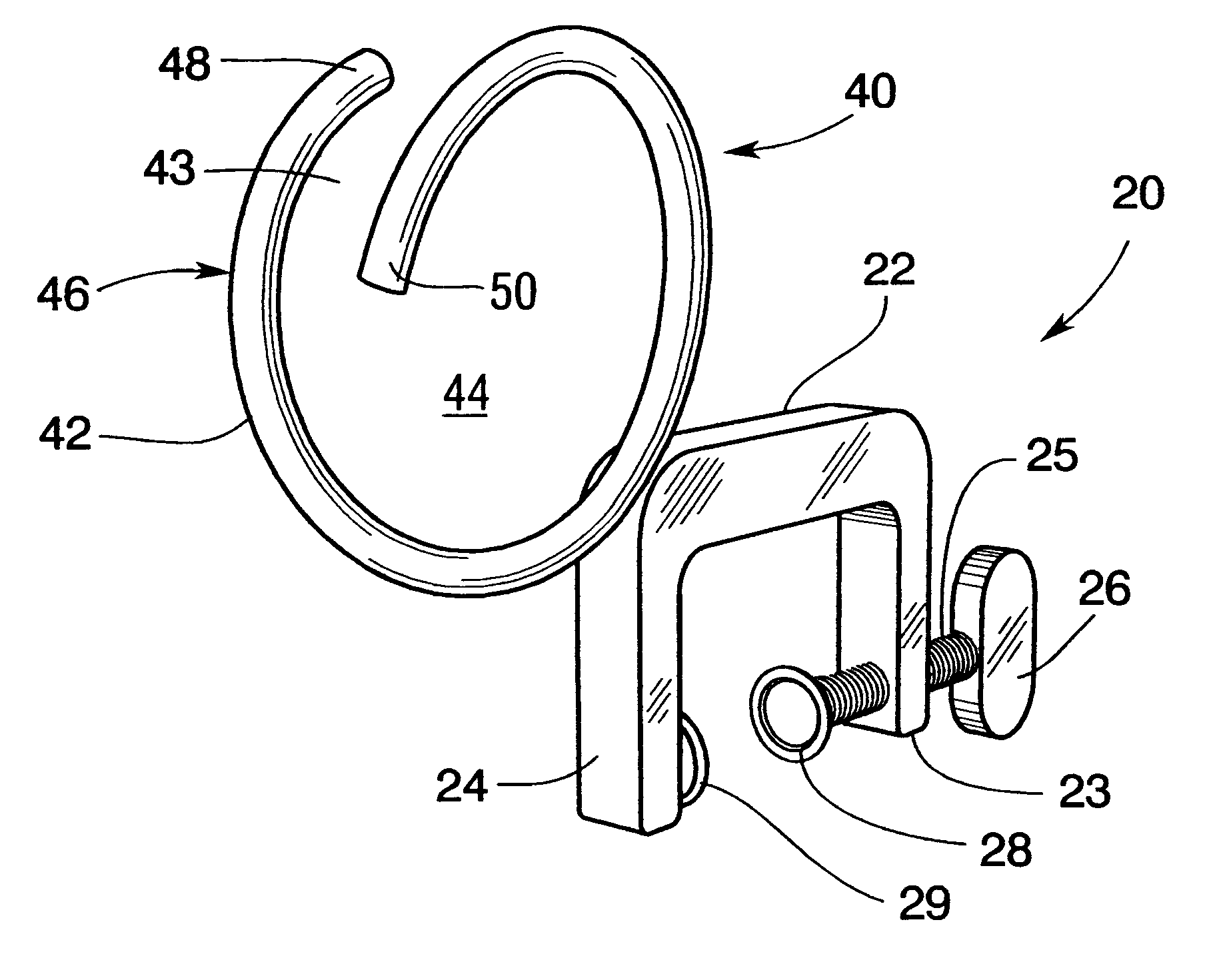
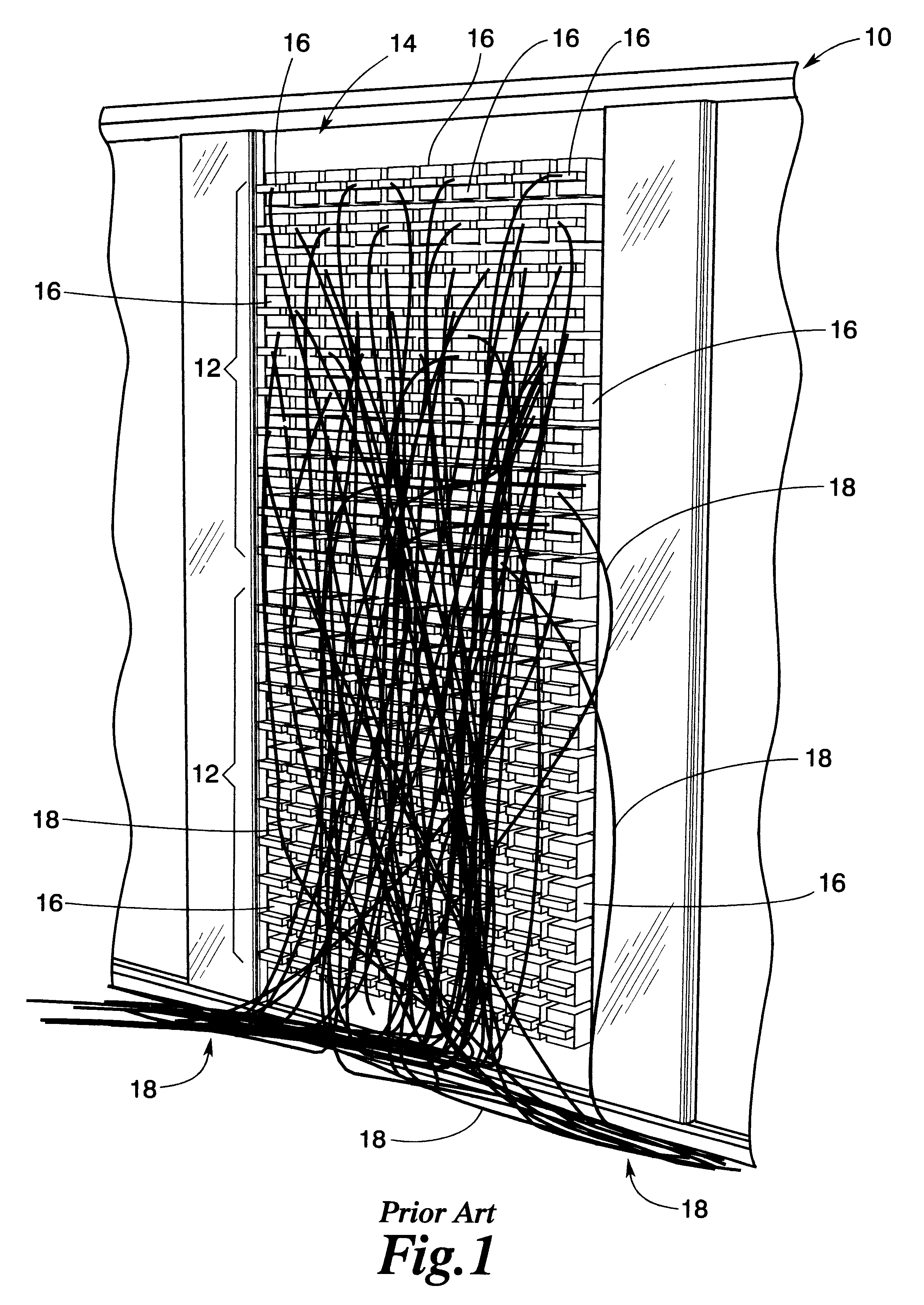
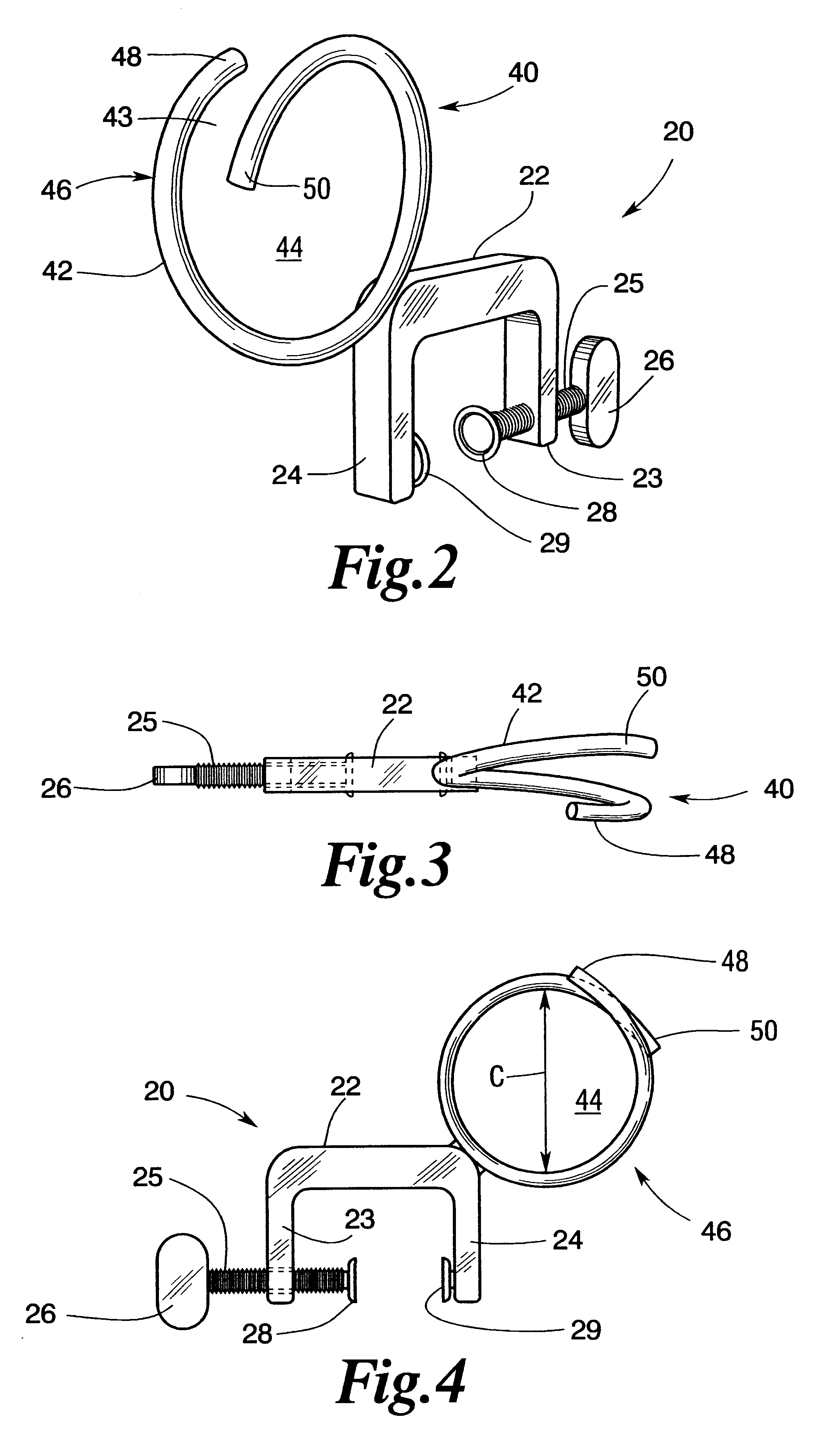
Referring now to the drawings for the purposes of illustrating the present preferred embodiments of the invention only and not for the purposes of limiting the same, the Figures illustrate embodiments of the present invention that may be used in connection with managing a plurality of wires / cables 18 attached to protector blocks 16 employed in the telecommunications industry. As the present Detailed Description proceeds, those of ordinary skill in the art will appreciate that the various embodiments of the present invention may be employed in a variety of settings and applications wherein it may be advantageous to support a plurality of wires, cables, etc. in an orderly fashion. Thus, the scope of protection afforded to the various embodiments of the present invention should not be limited to use in connection with the protector bays employed in connection with various telecommunications applications. The various embodiments are described herein as being adapted for use with "cables...


PUM


Abstract

A cable-supporting apparatus. One embodiment of the invention includes a rigid support member that may be attached to a framework that supports one or more components. At least one cable support member is attached to the rigid support member for receiving a portion of at least one cable therethrough. The cable support members may comprise split rings that each defines central cable-receiving area that is surrounded by rigid portions of the split ring.

Description

CROSS-REFERENCE TO RELATED APPLICATIONS NOT APPLICABLE.FEDERALLY SPONSORED RESEARCHNot applicable.1. Field of the InventionThe subject invention relates to guides and support members for members such as wires, cables and conduits and, more particularly, to guides for supporting multiple wires and / or cables while providing easy access thereto.2. Description of the Invention BackgroundOne might surmise that there are millions of miles of wires and cables distributed throughout the world for transmitting a variety of different electrical, optical, data, etc. signals between pieces of equipment. Regardless of the type of signal involved, a common installation scenario may involve one or more common locations wherein several of such wires and cables are brought together for interconnection with various electrical or optical components and / or other wires and cables. Junction boxes, electrical cabinets and racks of electrical components are examples of such locations.In applications wherei...

Claims


Application Information

Patent Timeline
Patent Type & Authority Patents(United States)
IPC IPC(8): F16L3/24H02G3/30
CPCF16L3/24H02G3/30
Inventor BJORKLUND, BRIAN P.
Owner BELLSOUTH INTPROP COR
Why Eureka
Try Eureka