Ultrasound receive beamforming apparatus using multi stage delay devices

a beamforming apparatus and ultrasonic technology, applied in the field of ultrasonic imaging apparatus, can solve problems such as increasing the complexity of a system

Inactive Publication Date: 2002-12-17
MEDISON CO LTD
View PDF11 Cites 12 Cited by
  • Summary
  • Abstract
  • Description
  • Claims
  • Application Information

AI Technical Summary

Problems solved by technology

In a multi-beam-forming apparatus, a different amount of delay should be applied for each beam and per channel, thus increasing the complexity of a system.

Method used


Image

  • Ultrasound receive beamforming apparatus using multi stage delay devices
  • Ultrasound receive beamforming apparatus using multi stage delay devices
  • Ultrasound receive beamforming apparatus using multi stage delay devices

Examples


Embodiment Construction

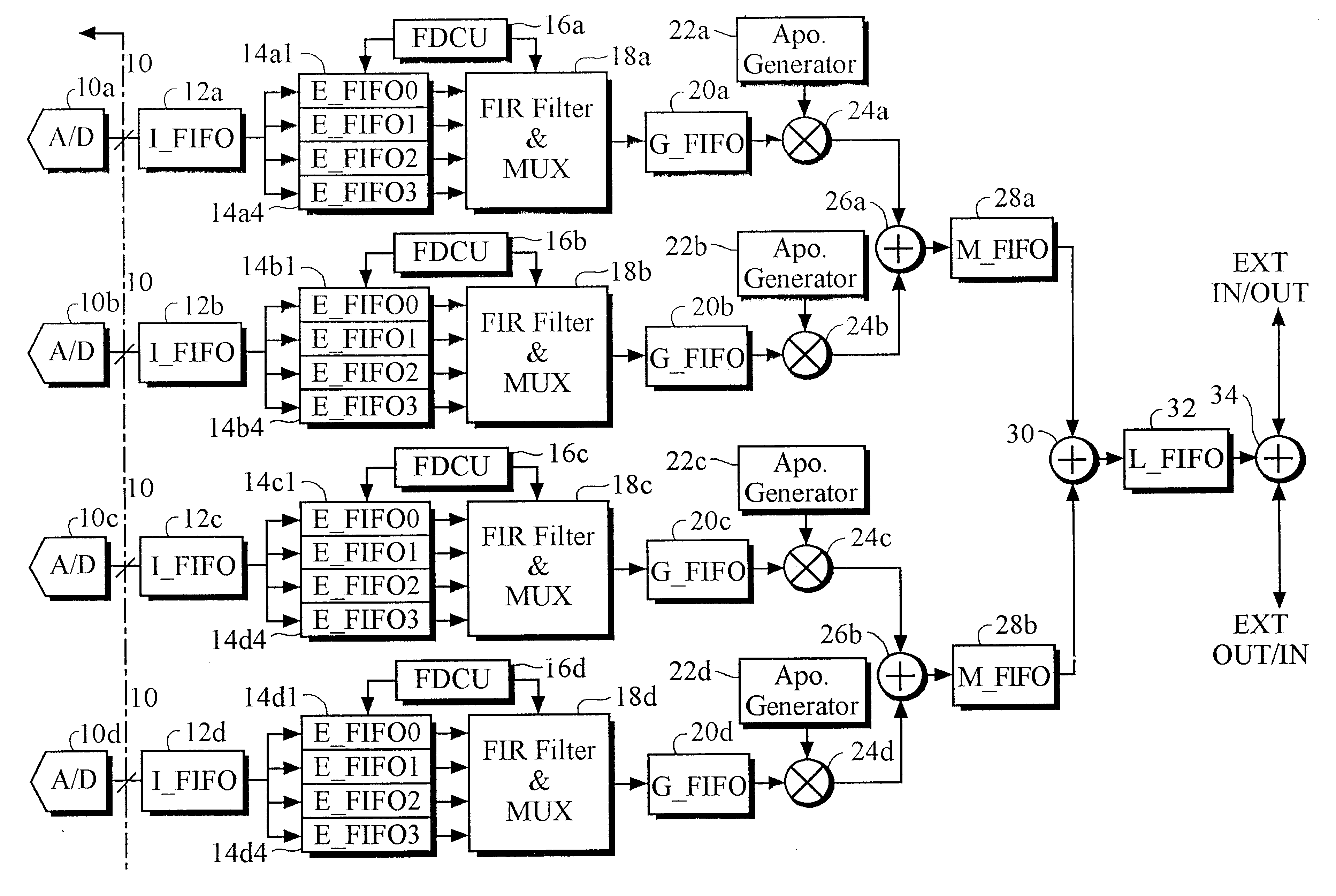
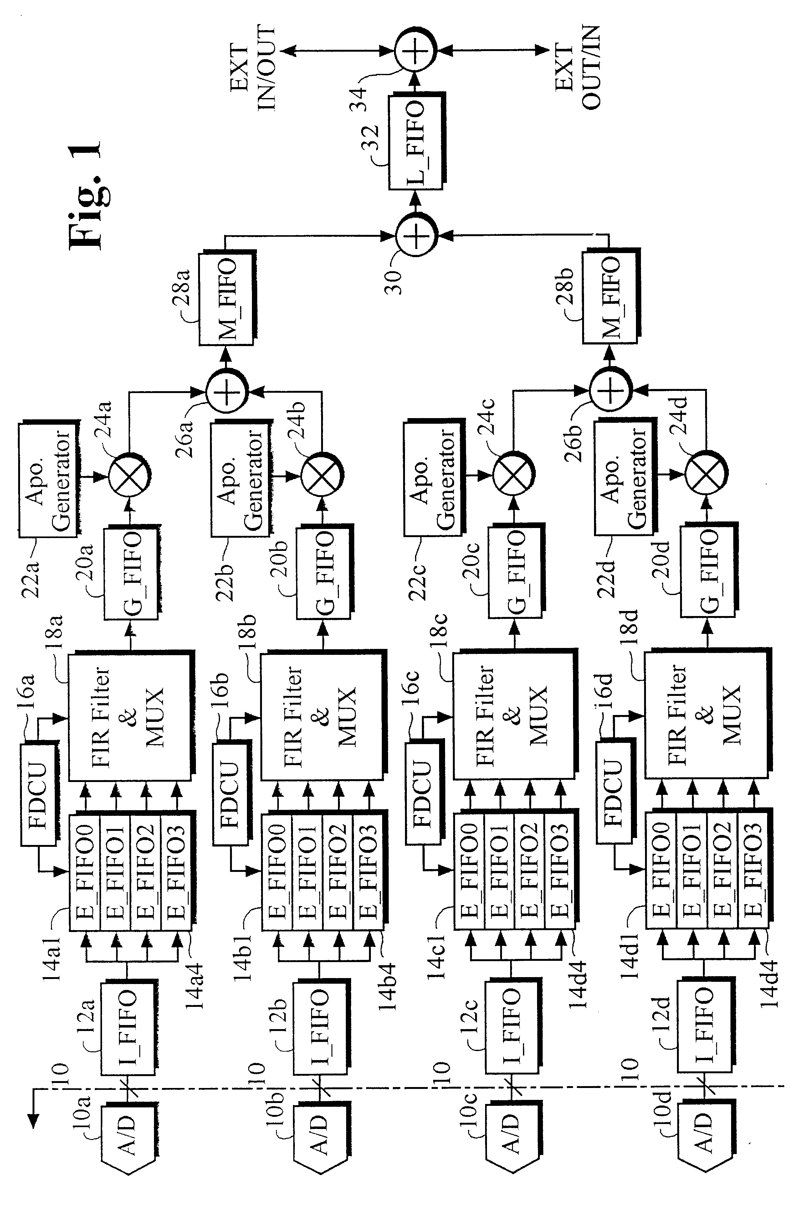
FIG. 1 shows a digital four-channel beamforming apparatus that can simultaneously process data samples received from four elements of an ultrasonic transducer array in accordance with one embodiment of the present invention. The beamforming apparatus shown in FIG. 1 applies coarse time delays in four distinct stages to each channel of data samples; filters and time-multiplexes each channel of time-delayed data; multiplies each channel of filtered, time-multiplexed data by an apodization factor derived from a predetermined apodization curve; and sums the data thereby obtained, to provide intermediate outputs. The intermediate outputs from the multiple beamforming apparatus are summed to provide time-multiplexed final outputs representing up to 4 focused beams, where each time interval of the time-multiplexed output data relates to a distinct receive beam. In an ultrasound imaging device where data from 64 channels are combined in a beamforming process to provide one receive scanline ...


PUM


Abstract

By using a novel structure of a beamformer which produce data for multiple receive scanlines in a time multiplexed manner, the size of the delay memory is reduced. An ultrasound receive beamforming apparatus for processing signals received from an array of transducers, comprises: a plurality of beamforming devices for applying delays to data samples of M channels. Each of said beamforming devices includes: a predetermined number of per-channel delay elements which provide first delays to the data samples of M channels, to provide delayed data per each channel and per each receive beam, first adders for adding the delayed data of not less than 2 channels provided from the per-channel delay elements, and multi-channel delay elements which provide second delays to the outputs of the first adders.

Description

Field of the InventionThe present invention relates to an ultrasound imaging apparatus using a digital beam focusing scheme. More particularly, the present invention relates to a receive beamforming apparatus for processing a plurality of scan lines or beams. It includes delay elements structured into multiple stages.Description of the Related ArtAs well known in the art, an ultrasound imaging system using an array of transducers includes a phased, convex or linear array of multiple transducers. Such a system includes multiple channels, each channel having a transmitter and a receiver connected to a corresponding transducer. The transmitter applies ultrasound pulses to an object such as one in a human body. To focus the transmitted ultrasound energy to a certain point in the object, sequential time delays are applied to the pulses. The amount of delay for each pulse is determined in a way that the transmitted pulses reach a target point simultaneously. These pulses pass through dive...

Claims


Application Information

Patent Timeline
Patent Type & Authority Patents(United States)
IPC IPC(8): G01S7/52G10K11/34G10K11/00
CPCG01S7/52034G01S7/52095G10K11/346A61B8/00
Inventor BAE, MOO-HO
Owner MEDISON CO LTD
Why Eureka
Try Eureka