Magnetic head supporting apparatus having thermally insulated read/write IC mounted on arm portions thereof

a technology of magnetic head support and read/write ic, which is applied in the direction of magnetic recording, instruments, data recording, etc., can solve the problems of high temperature of the ic itself, inability to accurately read/write from or to the magnetic disc, and distortion of the signal, etc., and achieves the effect of convenient mounting

Inactive Publication Date: 2002-12-24
HITACHI GLOBAL STORAGE TECH JAPAN LTD
View PDF7 Cites 23 Cited by
  • Summary
  • Abstract
  • Description
  • Claims
  • Application Information

AI Technical Summary

Benefits of technology

Accordingly, an object of the present invention is to provide a head supporting apparatus which is structured so as to mount a read / write IC in an arm portion for supporting a head, radiate the heat of the read / write IC and generate no thermal expansion of the arm itself, and can be easily mounted.

Problems solved by technology

When the reduction occurs impedance, a distortion is generated in the signal and it is impossible to accurately read / write from or to the magnetic disc.
As a result, since the read / write IC mounted on the arm for supporting the magnetic head consumes a large amount of electric power with a little volume, a temperature of the IC itself becomes very high is and there is a possibility that a thermal fracture will occur.
Firstly, the arm portion for supporting the head is designed so as to make it compact and light, and therefore, when the heat is directly radiated to the arm portion, the arm itself is deformed due to a thermal expansion. As a result, an angle of attitude of the head is changed and a positioning accuracy is deteriorated Accordingly, the IC is mounted near a root portion of the arm where the thermal expansion of the arm can be ignored. However, this structure limits the degree to which the wire between the read / write IC and magnetic head can be shortened and thus runs counter to an original object thereof.
As mentioned above, in accordance with the conventional method of radiating the heat of the read / write IC by means of the radiating fins provided in the arm portion for supporting the magnetic head, there is a problem that the positioning accuracy of the magnetic head is deteriorated due to the deformation caused by the thermal expansion of the arm itself.

Method used


Image

  • Magnetic head supporting apparatus having thermally insulated read/write IC mounted on arm portions thereof
  • Magnetic head supporting apparatus having thermally insulated read/write IC mounted on arm portions thereof
  • Magnetic head supporting apparatus having thermally insulated read/write IC mounted on arm portions thereof

Examples


Embodiment Construction

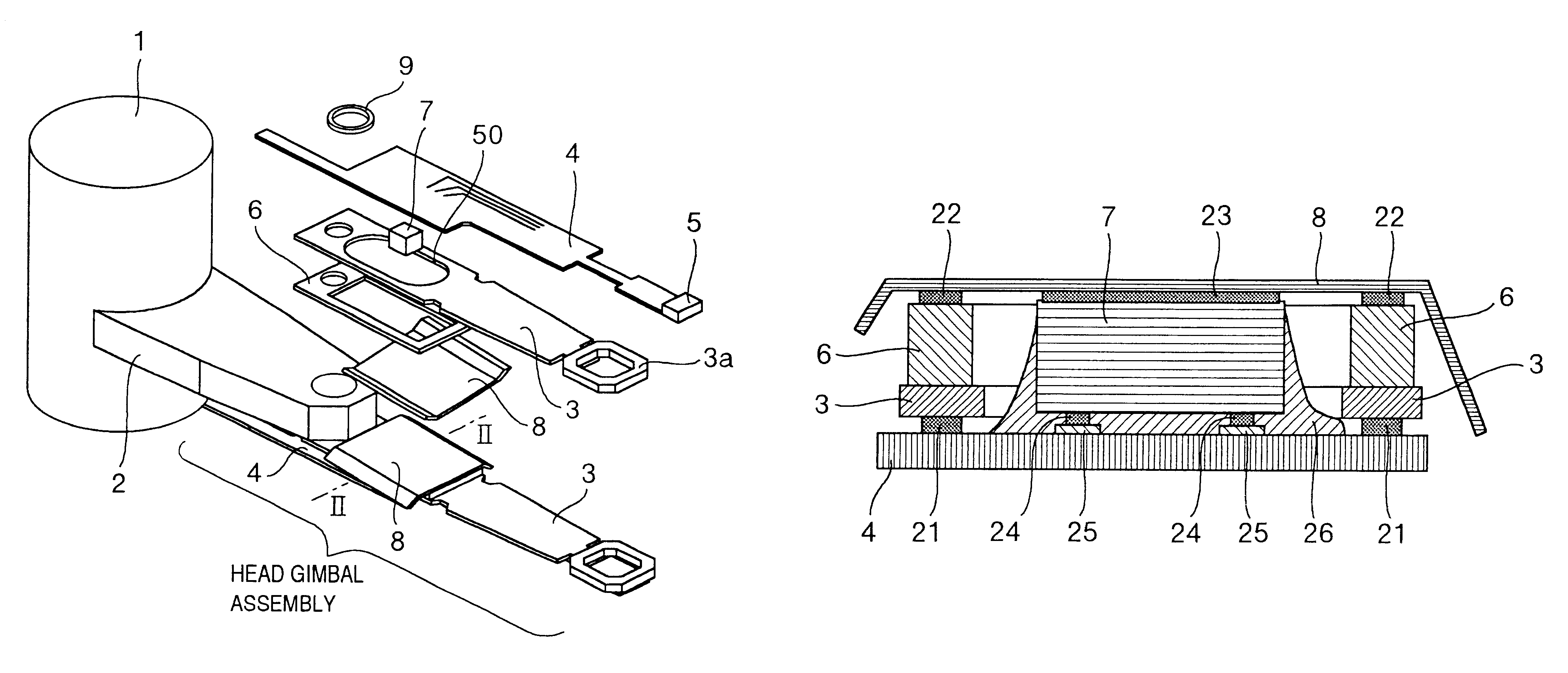
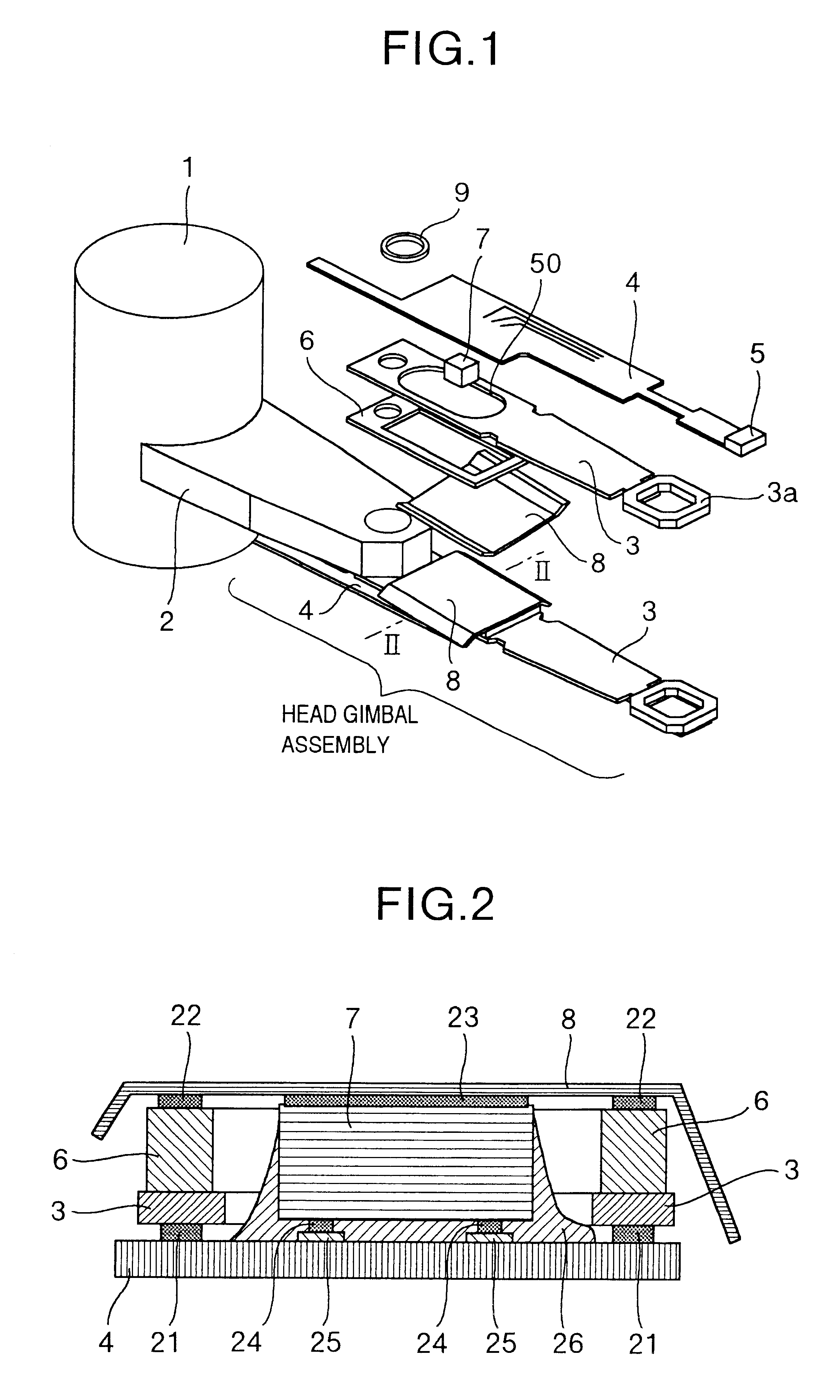
A description will be given in detail of an embodiment of the present invention with reference to FIGS. 1 and 2. FIG. 1 is a view showing a structure of an embodiment of a head supporting apparatus of the present invention and FIG. 2 is a cross sectional view of an IC chip inserting portion of the embodiment shown in FIG. 1.

As shown in FIG. 1, a basic structure of the embodiment of a head supporting apparatus of the present invention comprises a hollow cylindrical rotary shaft 1 which is inserted and fixed onto a drive shaft provided on a magnetic disc apparatus, a base arm 2 which is mounted to the rotary shaft 1 and an arm suspension 3 which is mounted to the base arm 2 by fastening means 9. In the arm suspension 3, there is provided a gimbal 3a which, at a forward end, supports a slider having a read / write magnetic head 5 for recording and reproducing information on a magnetic disc. In the present embodiment, the slider having the magnetic head 5 is mounted to a wiring flexible p...


PUM

PropertyMeasurementUnit
heataaaaaaaaaa
flexibleaaaaaaaaaa
angleaaaaaaaaaa

Abstract

A magnetic head supporting apparatus includes a magnetic head for reading and writing information on a magnetic disc, a slider having the magnetic head, and a suspension for supporting the slider. An IC chip for controlling a signal of the magnetic head is mounted on a first surface of a heat insulating substrate, and a second surface of the heat insulating substrate opposite to the first surface thereof is mounted to the suspension.

Description

The present invention relates to a head supporting mechanism portion of a magnetic disc apparatus, and particularly to a head supporting apparatus in which an IC chip is mounted on an arm portion thereof and a magnetic disc apparatus using such a head supporting apparatus.In the conventional magnetic disc apparatus, when improving a transfer speed, an impedance reduction occurs in a wire extending from a -read / write IC for controlling read / write signals to a magnetic read / write head. When the reduction occurs impedance, a distortion is generated in the signal and it is impossible to accurately read / write from or to the magnetic disc. Then, it is necessary to mount the read / write IC for amplifying the read / write signal as close to the magnetic head as possible.Then, in JP-A-3-187295, there is disclosed a structure such that the read / write IC is directly mounted on the arm portion for supporting the magnetic head.In this structure, heat radiating fins are formed in an arm portion (sus...

Claims


Application Information

Patent Timeline
Patent Type & Authority Patents(United States)
IPC IPC(8): G11B5/48
CPCG11B5/486G11B5/4833
Inventor SHIMIZU, HAYATONAKAZATO, NORIOMATSUMOTO, MASAAKISHIROISHI, YOSHIHIROTOKUYAMA, MIKIOSHIMIZU, TOSHIHIKONAKAMURA, SHIGEO
Owner HITACHI GLOBAL STORAGE TECH JAPAN LTD
Why Eureka
Try Eureka