Device for the transfer of exhaust gas from the exhaust collector of a supercharged internal combustion engine to the inlet conduit thereof

a technology of exhaust gas and exhaust collector, which is applied in the direction of engine components, internal combustion piston engines, non-fuel substance addition to fuel, etc., can solve the problems of charging air in the inlet conduit being higher than the gas pressure in the exhaust h collector, charging air flow and the pressure conditions between the exhaust collector and the conduit,

Inactive Publication Date: 2003-01-07
MOTORTESTCENT MTC
View PDF8 Cites 67 Cited by
  • Summary
  • Abstract
  • Description
  • Claims
  • Application Information

AI Technical Summary

Problems solved by technology

One problem for specifically short way systems is that if the turbo supercharge is made effective, the pressure of the charging air in the inlet conduit will become higher than the gas pressure in the exhaust H collector.
A particular problem in connection with the use of a venturi device for sucking in the EGR gasses is that the charging air flow and the pressure conditions between the exhaust collector and the inlet conduit vary in dependence of the different load points of the internal combustion engine.
However, a disadvantage with such a bypass of the charging air is that the pressure recovering-is not achieved and that the venturi device gets a bad efficiency.
However, in practice, a construction of this type becomes complicated and costly, and the rubber material has a limited life in the tough environment in which the canal wall steadily works, due to alternating contractions and expansions.

Method used


Image

  • Device for the transfer of exhaust gas from the exhaust collector of a supercharged internal combustion engine to the inlet conduit thereof
  • Device for the transfer of exhaust gas from the exhaust collector of a supercharged internal combustion engine to the inlet conduit thereof
  • Device for the transfer of exhaust gas from the exhaust collector of a supercharged internal combustion engine to the inlet conduit thereof

Examples


Embodiment Construction

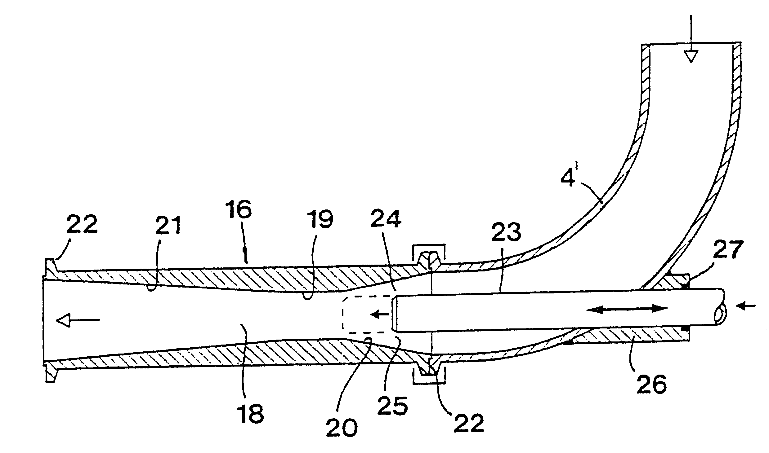
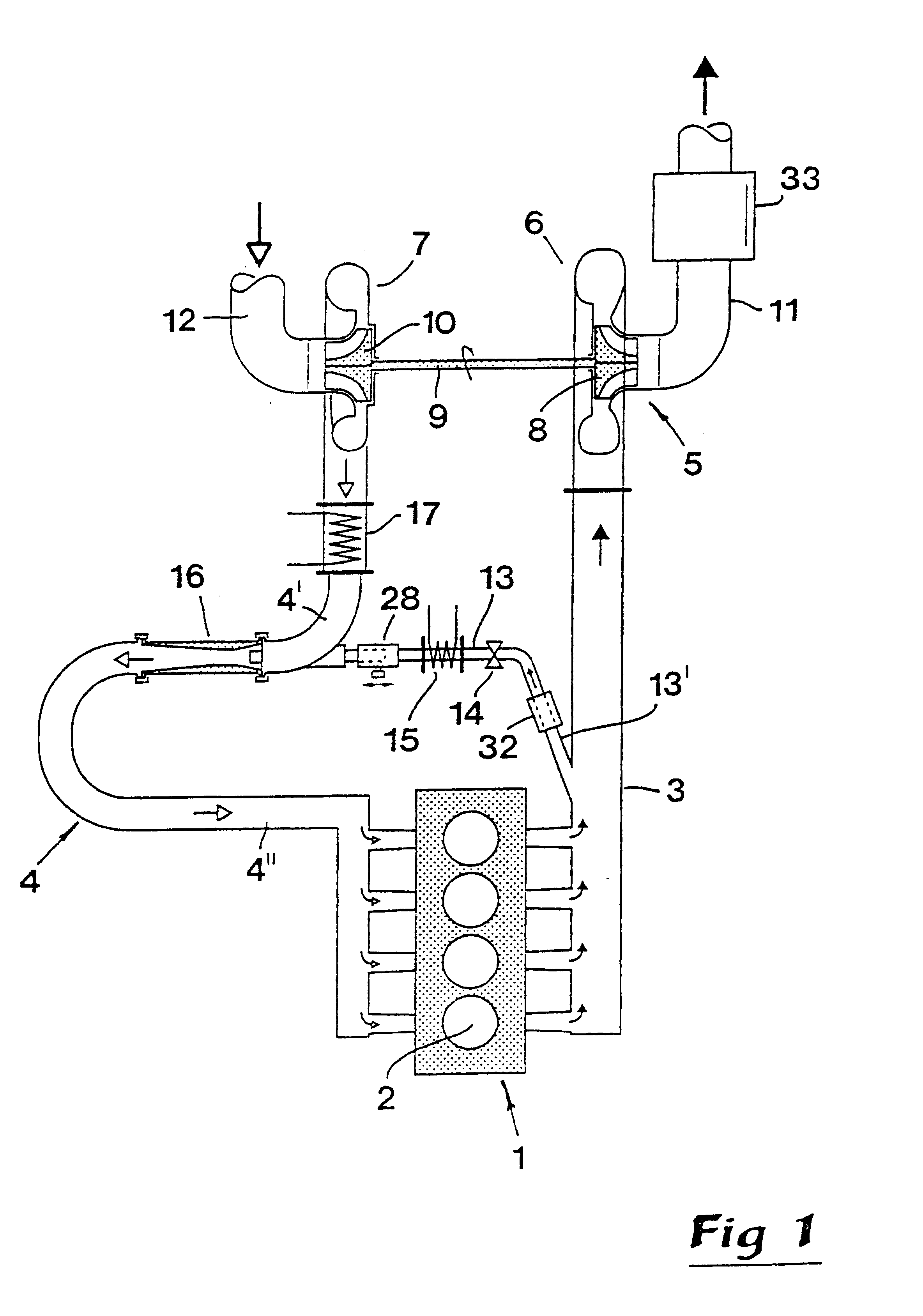
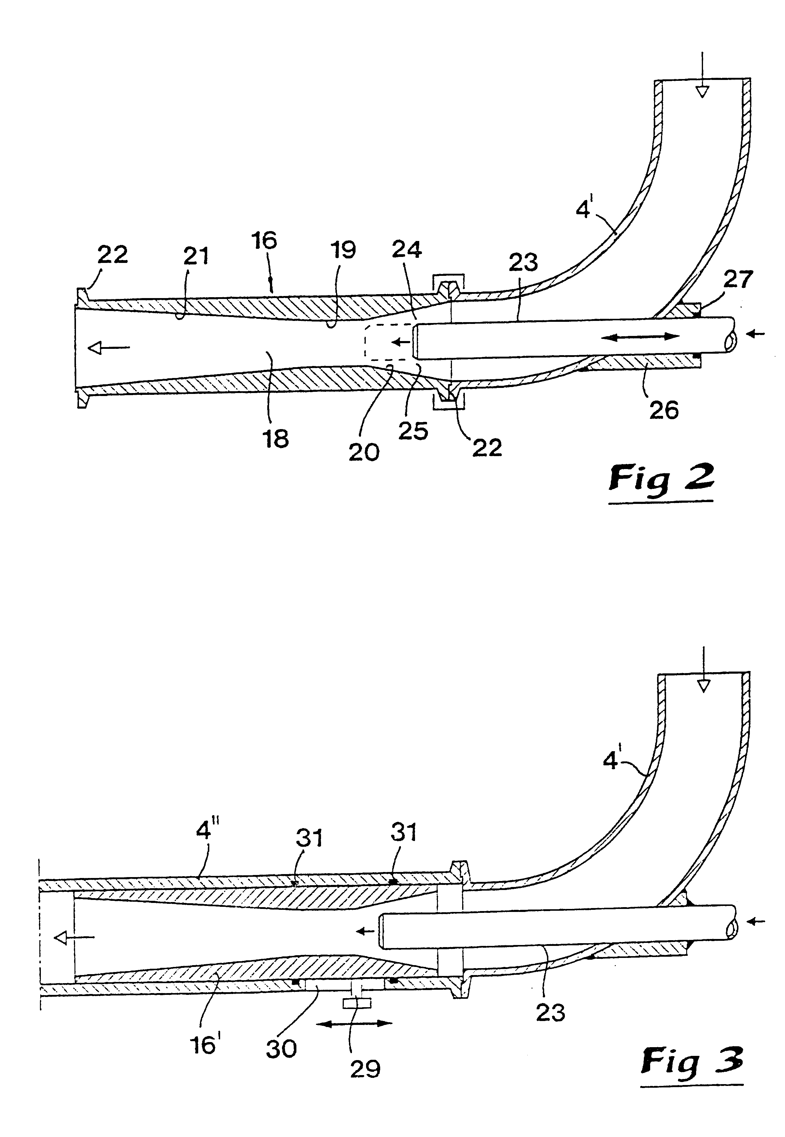
In FIG. 1, reference numeral 1 designates generally an internal combustion engine of the piston engine type, that comprises a plurality of cylinders 2. In practice, this motor may consist of, e.g., a four-stroke Diesel engine intended for heavier vehicles such as trucks, busses or similar. At an outlet end, the engine 1 has an exhaust collector 3 that may have a most varied shaping, but comprises a number of branch conduits or canals connected to a manifold for evacuating the exhaust gasses from the engine. At the inlet side of the engine is an inlet conduit designated 4 in its entirety, for the supply of charging air or gas via branch canals to the different cylinders of the engine.

For feedback of exhaust gasses or EGR gasses from the exhaust collector 3 to the inlet side of the engine is provided a turbo unit designated 5 in its entirety, which unit in the usual way comprises on one hand a turbine 6 and on the other hand a compressor 7. A turbine wheel 8 actuating in the turbine i...


PUM


Abstract

A device for transferring EGR gasses from the exhaust collector of a supercharged internal combustion engine to its inlet conduit includes, besides a supercharge unit, a venturi device having the purpose of sucking the EGR gasses from the exhaust collector into the inlet conduit in order to overcome the high gas pressure in the pressurized charging air in this conduit. In order to adjust the amount of sucked-in EGR gas to the different load points, under which the engine works, an injector tube is arranged in the inlet section to the canal of the venturi device, through which injector tube the EGR gasses are led into the inlet conduit. The free end of this injector tube delimits, together with the surrounding canal wall, a ring-shaped passage, whose cross-sectional area may be varied by an axial relative motion between the injector tube and the venturi device.

Description

This invention relates to a device for the transfer of exhaust gas from the exhaust collector of a supercharged internal combustion engine to the inlet conduit thereof, comprising a supercharge unit with a turbine connected to the exhaust collector, the wheel of which turbine being rotatable by means of flowing exhaust gasses from the exhaust collector and drivingly connected with an impeller of a compressor provided in the inlet conduit, which compressor is connected to on one hand an external inlet conduit part for sucking in air from outside by means of the impeller, and on the other hand to said inlet conduit for feeding of pressurized charging air to the engine, and a transfer conduit extending between the exhaust collector and the inlet conduit for, when necessary, transferring exhaust gasses from the exhaust collector to the inlet conduit in and for mixing with the charging air before the latter is fed to the engine, a venturi device being provided in the inlet conduit, of th...

Claims


Application Information

Patent Timeline
Patent Type & Authority Patents(United States)
IPC IPC(8): F02M25/07F02B37/00
CPCF02M25/0713F02M25/0722F02M25/0724F02M25/0735F02M25/0793F02M25/0707Y02T10/121F02M25/0746F02M25/0727F02M26/40F02M26/05F02M26/10F02M26/19F02M26/21F02M26/23F02M26/30F02M26/70
Inventor LUNDQVIST, ULF
Owner MOTORTESTCENT MTC
Why Eureka
Try Eureka