Clutch connection control system

a control system and clutch technology, applied in mechanical actuated clutches, mechanical equipment, transportation and packaging, etc., can solve the problems of delicate difference between the end timing of the clutch connection, the operation of the drive system for driving the clutch is not ended, and the time required for ending the automatic speed change has not been examined at all, so as to shorten the time required, prevent the degradation of riding comfort upon the clutch connection, and the effect of good operability

Inactive Publication Date: 2003-01-07
HONDA MOTOR CO LTD
View PDF12 Cites 50 Cited by
  • Summary
  • Abstract
  • Description
  • Claims
  • Application Information

AI Technical Summary

Benefits of technology

An object of the present invention is to solve the above-described technical problems of the related art and to provide a clutch connection control system capab

Problems solved by technology

However, even when the turning speed difference between the clutch drive side and clutch driven side becomes zero, the operation of the drive system for driving the clutch is not ended yet.
According to the above-described first related art, however, it has not been examined at all to shorten a time required for ending automatic speed change by returning respective portions of the drive system to initial positions after the turning speed difference between the clutch drive side and clutch driven side becomes zero.
Accordingly, a delicate

Method used


Image

  • Clutch connection control system
  • Clutch connection control system
  • Clutch connection control system

Examples


Embodiment Construction

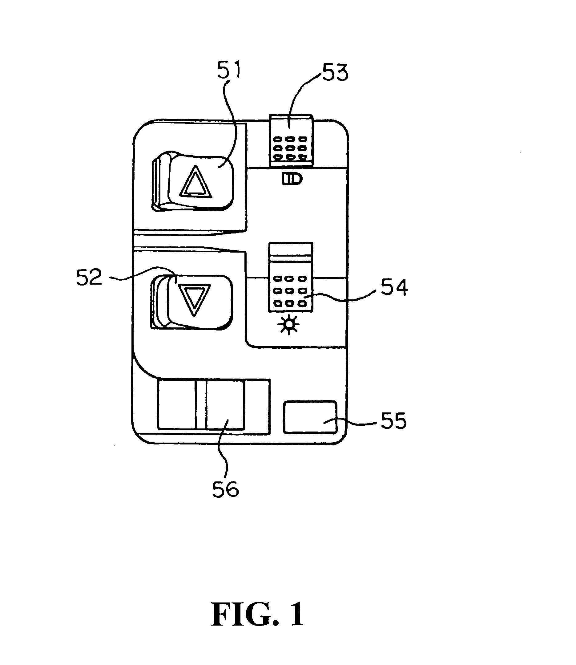
Hereinafter, an embodiment of the present invention will be described in detail with reference to the drawings. FIG. 1 is a plan view of an operational portion of a vehicle including a motor-driven speed change apparatus including a clutch connection control system of the present invention.

The operational portion includes a shift-up switch 51 and a shift-down switch 52 for carrying out motor-driven gear shift; a dimmer switch 53 for switching the direction of a headlamp upward or downward; a lighting switch 54 for switching a lighting state of the headlamp between the lighting-up and lighting-out states; and an engine start switch 55 and an engine stop switch 56. In this embodiment, the shift position is shifted up or shifted down by one step each time the shift-up switch 51 or shift-down switch 52 is depressed.

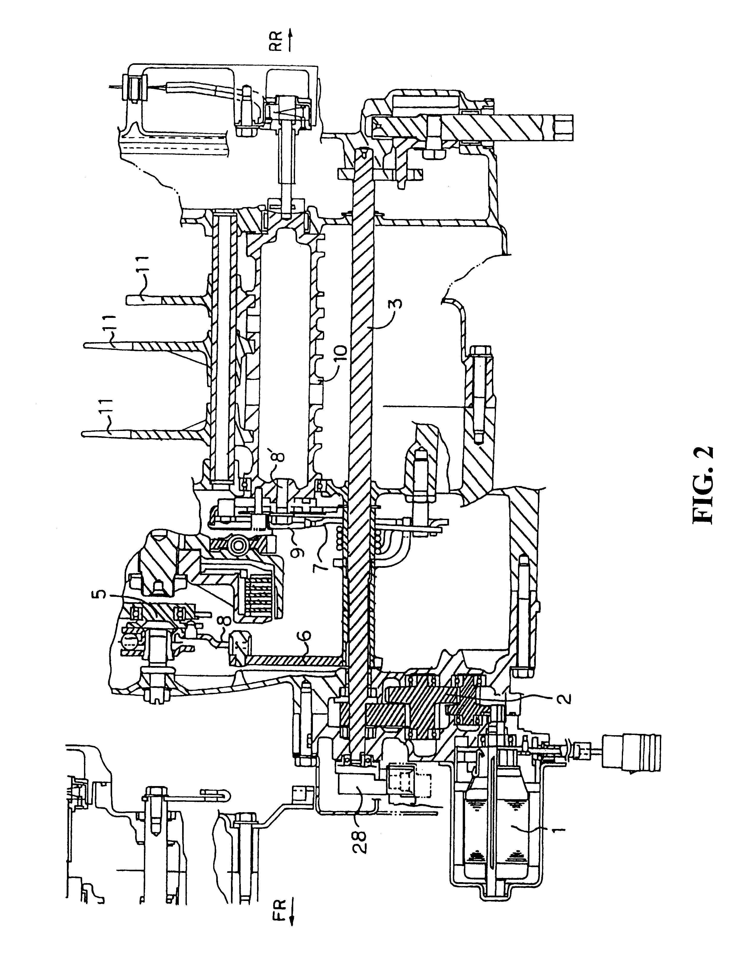
FIG. 2 is a partial sectional view showing the configuration of a principal portion of a drive system of the motor-driven speed change apparatus to which the present inventio...


PUM


Abstract

To provide a clutch connection control system capable of shortening a time required for clutch connection, preventing the degradation of riding comfort upon clutch connection, and ensuring good operability. A separation distance, that is, a shift amount of a clutch driven side from a clutch drive side is controlled by a clutch release mechanism driven by a drive motor. A drive side turning speed detecting portion detects a turning speed Nin of the drive side. A driven side turning speed detecting portion detects a turning speed Nout of the driven side. A turning speed difference detecting portion detects a difference Nd between the detected drive side turning speed Nin and driven side turning speed Nout. A rate-of-change detecting portion detects a time-dependent rate of change .DELTA.Nd of the detected turning speed difference Nd. A control portion performs clutch connection at a second speed until an absolute value A (Nd) of the turning speed difference becomes a specific value or less and performs clutch connection at a third speed higher than the second speed after the absolute value A (Nd) of the turning speed difference becomes the specific value or less.

Description

BACKGROUND OF THE INVENTION1. Field of the InventionThe present invention relates to a clutch connection control system for a motor-driven speed change apparatus in which gear shift and disconnection and connection of a clutch are performed by using an electric motor. In particular, the present invention relates to a clutch connection control system for variably controlling a connection speed of the clutch on the basis of turning speeds of a clutch drive side and a clutch driven side.2. Description of Related ArtAs opposed to a related speed change apparatus for carrying out gear shift by operating both a clutch pedal (or clutch lever) and a gear shift lever, a motor-driven speed change apparatus for electrically carrying out gear shift by using a motor has been known, for example, from Japanese Patent Laid-open No. Hei 1-122741.To shorten a time required for clutch connection and improve riding comfort upon clutch connection, the above related art speed change apparatus is configur...

Claims


Application Information

Patent Timeline
IPC IPC(8): F16D48/00F16D48/06B60W10/08B60W10/10B60W10/02F16H63/46
CPCF16H63/46F16D48/064B60K2741/225B60W2510/0283B60W2510/1015F16D2500/3021F16D2500/3026F16D2500/30415F16D2500/30426F16D2500/3067F16D2500/3069F16D2500/30808F16D2500/3108F16D2500/31493F16D2500/3166F16D2500/50239F16D2500/5122F16D2500/525F16D2500/70235F16D2500/70241F16D2500/7041F16D2500/70488F16D2500/70626F16D2500/7109B60W10/02B60W10/10B60W30/1819
Inventor OTA, ATSUONAGATSUYU, TOSHIYA
Owner HONDA MOTOR CO LTD
Why Eureka
Try Eureka