Pressing tool for pressing coupling elements

a technology of coupling elements and pressing tools, which is applied in the direction of couplings, mechanical devices, clutches, etc., can solve the problems of affecting the operation the operation duration per stroke of the piston cylinder unit is relatively long, and the availability of electrical connection sources on building sites is often very limited

Inactive Publication Date: 2003-01-28
VON ARX AG
View PDF10 Cites 34 Cited by
  • Summary
  • Abstract
  • Description
  • Claims
  • Application Information

AI Technical Summary

Problems solved by technology

However the availability of electrical connection sources on building sites is often very limited.
All previously known systems have a relatively low delivery power and accordingly the operational duration per stroke of the piston cylinder unit to be actuated is relatively long.
This results also in an extremely compact arrangement with correspondingly short hydraulic conduits and accordingly leads to a relatively light pressing tool, even with the incorporated battery.

Method used


Image

  • Pressing tool for pressing coupling elements
  • Pressing tool for pressing coupling elements
  • Pressing tool for pressing coupling elements

Examples


Embodiment Construction

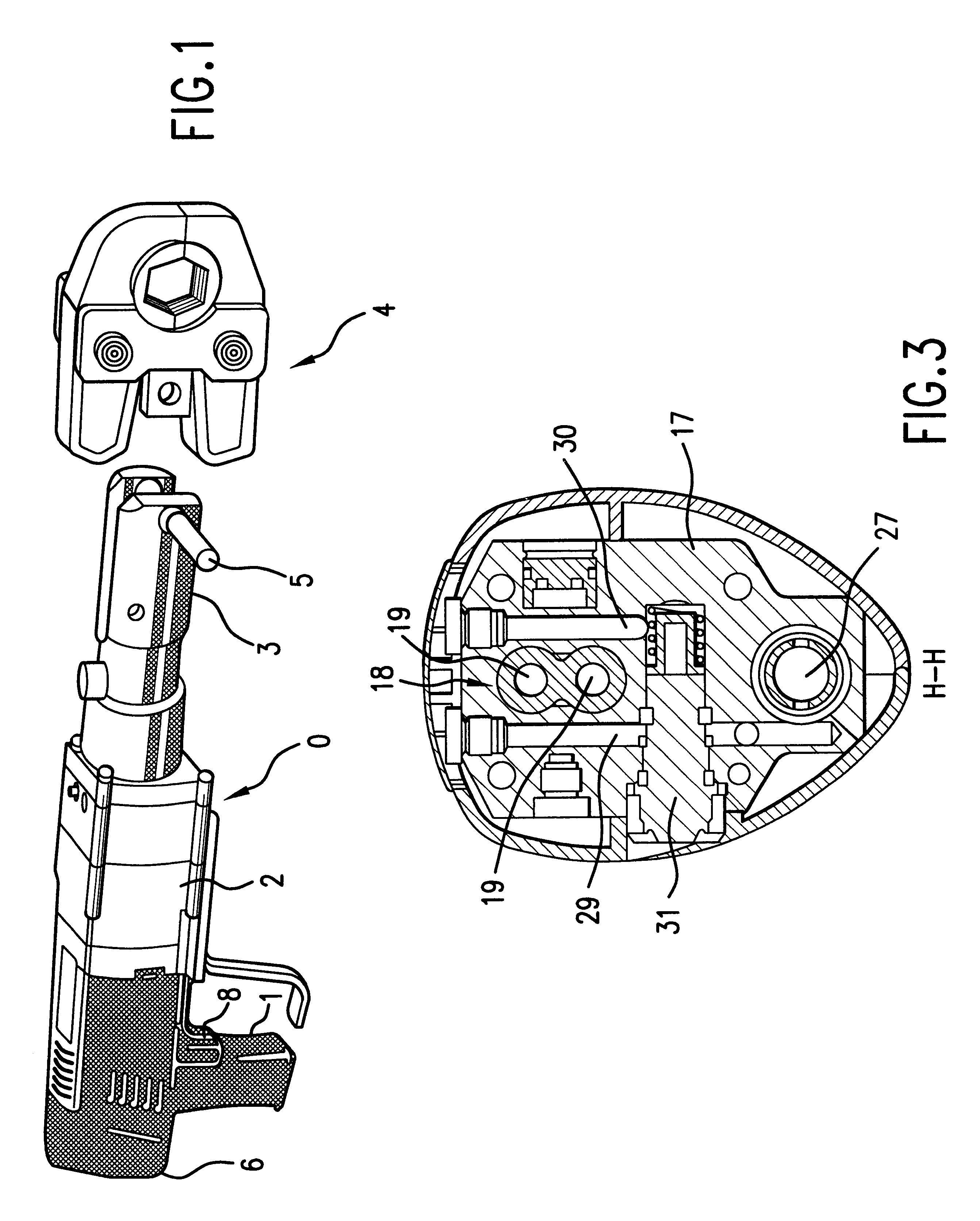
A pressing tool 0 is an electrohydraulic apparatus which can be a battery-operated apparatus. The pressing tool 0 has a pressing tool function unit 2 on which there is formed a grip 1. In the rearward extension on the function unit 2, a battery housing 6 is formed as a removable part. In the forward extension of the pressing tool function unit 2 there is recognizable a fork-like receiver 3. In the fork-like receiver 3 is held a clamping pincer 4 in a secured manner in the receiver 3, with a security bolt 5. For the actuation of the apparatus there is a release switch 8.

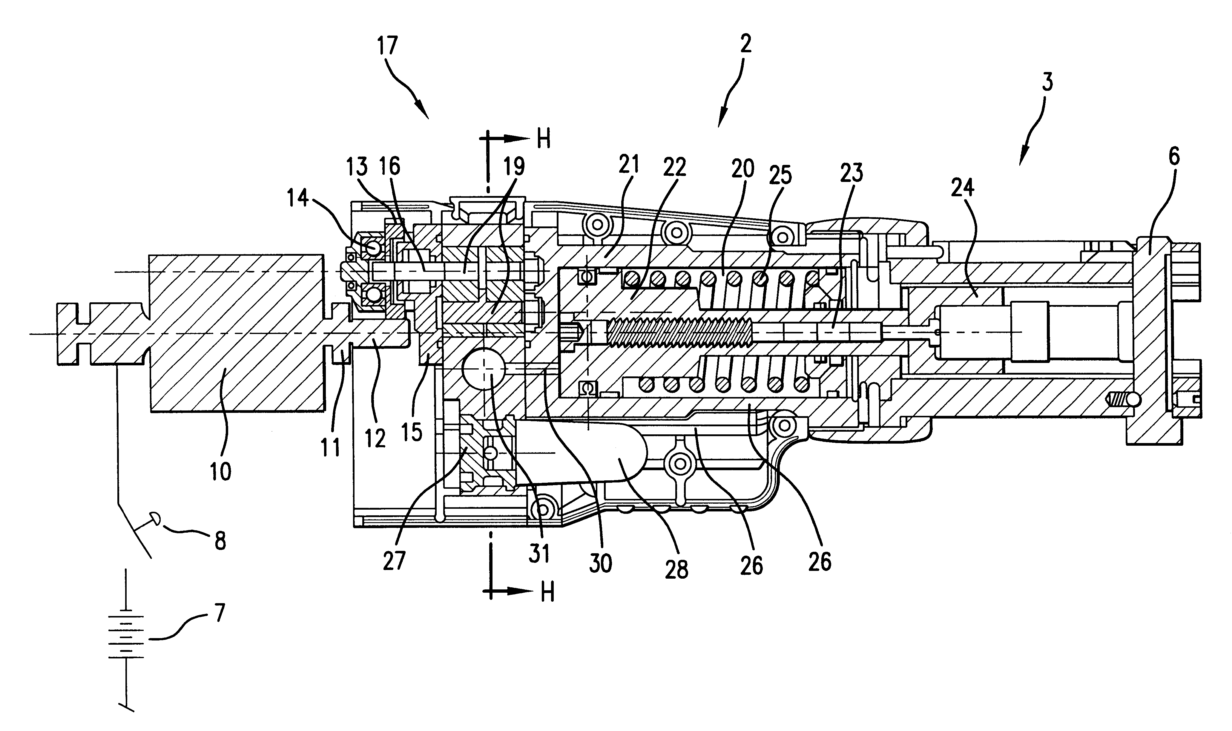
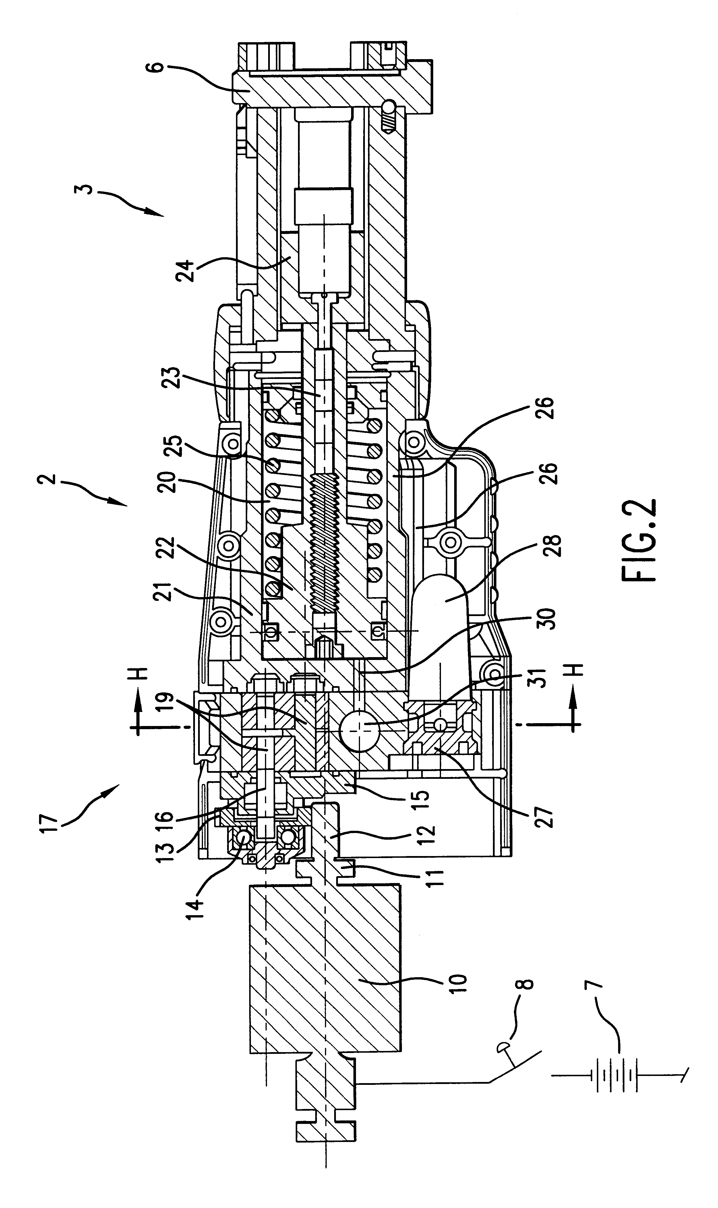
The actual construction of the pressing tool function unit 2 is shown in FIG. 2. The drive is performed by an electric motor 10 which is supplied by the battery feed 7. The release switch 8 is arranged between the electric motor 10 and the battery 7. The electric motor 10 has an output shaft 11 with an end-side output pinion 12 that meshes with a gearwheel 13 which is mounted on a gear output shaft 16. The gear output...


PUM

PropertyMeasurementUnit
pressureaaaaaaaaaa
volumeaaaaaaaaaa
restoring movementaaaaaaaaaa

Abstract

A pressing tool having an electric motor fed by a battery. The electric motor drives a gear pump with two rotor shafts which are accommodated in a hydraulic block. The rotor shafts are mounted in a gear housing on one side of the hydraulic block and in a cylinder housing of a piston cylinder unit which bears on an other side of the hydraulic block. This gear pump uses an extremely simple construction manner and simultaneously achieves a high delivery volume. The high delivery volume leads to an extremely low loading of the battery, by which its operational duration is increased.

Description

1. Field of the InventionThis invention relates to a portable, hydraulically functioning pressing tool for the pressing of coupling elements, with a fork-like receiver and with a clamping pincer which is held in the receiver and which is actuatable by a piston cylinder unit with an integrated restoring spring.2. Description of Related ArtPortable, hydraulically functioning pressing tools are known and used for pressing coupling elements, such as press sleeves, press fittings, connecting sleeves, tube sections inserted into one another and likewise. The pressing tools have a clamping pincer with clamping jaws which form a pressing space for receiving the coupling elements to be pressed. The pressing force required for the pressing is delivered by a generally hydraulic drive.Because the apparatus of interest here is preferably used on building sites it is an electrically driven apparatus. By way of example, U.S. Pat. No. 5,040,400 shows a pneumatically functioning apparatus. An electr...

Claims


Application Information

Patent Timeline
Patent Type & Authority Patents(United States)
IPC IPC(8): B25B27/02B25B27/10
CPCB25B27/10
Inventor AMHERD, RENE
Owner VON ARX AG
Why Eureka
Try Eureka