Dual-inlet gear pump with unequal flow capability

a technology of unequal flow capacity and gear pump, which is applied in the direction of machine/engine, liquid fuel engine, rotary/oscillating piston pump components, etc., to achieve the effect of increasing the volume of fluid

Active Publication Date: 2006-08-22
HAMILTON SUNDSTRAND CORP
View PDF18 Cites 29 Cited by
  • Summary
  • Abstract
  • Description
  • Claims
  • Application Information

AI Technical Summary

Problems solved by technology

This gear tooth space volume is thus partially filled with carry-over air, and does not accept a full tooth space of new air / oil mixture from the inlet.

Method used


Image

  • Dual-inlet gear pump with unequal flow capability
  • Dual-inlet gear pump with unequal flow capability
  • Dual-inlet gear pump with unequal flow capability

Examples


Embodiment Construction

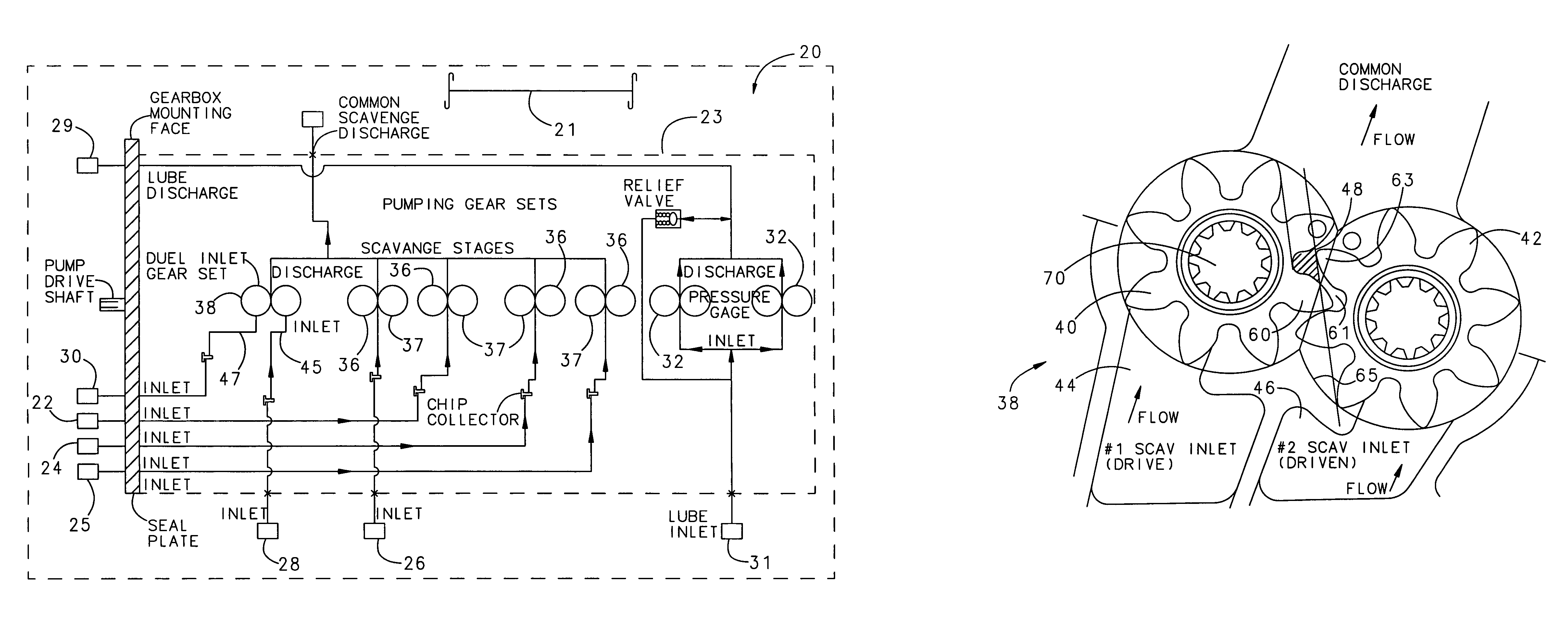
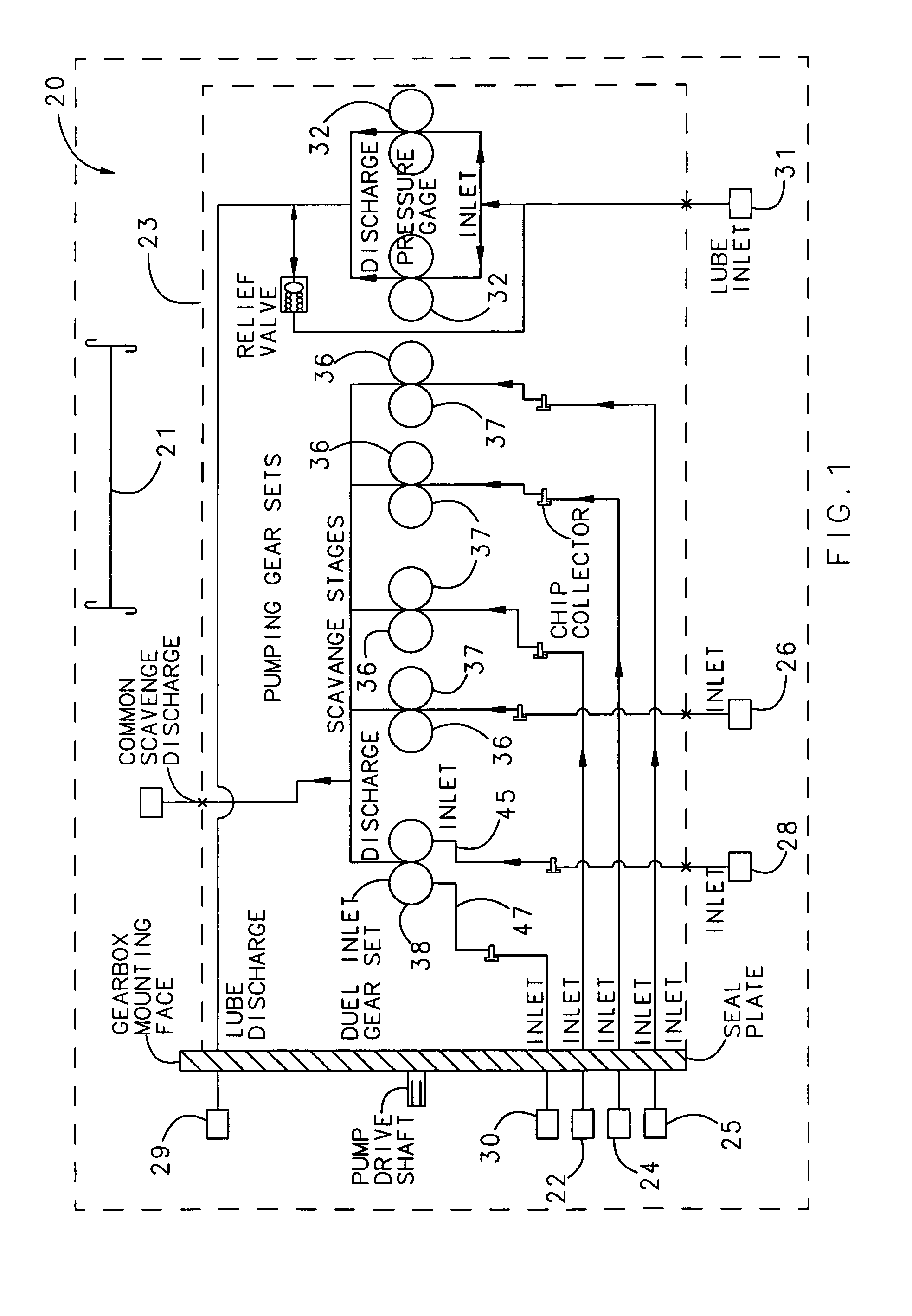
[0013]A jet engine 20 is illustrated schematically in FIG. 1. As shown, a drive shaft 21 of the jet engine is powered by combustion, and driven to rotate. A main gearbox 30 takes this rotation and powers accessory components. Among the accessory components are an oil lubrication and scavenging pump 23 that delivers oil to and from gearbox 30 and its accessory components. Oil lubrication and scavenging pump 23 also delivers oil to and from bearings 22, 24, 25 and 26 for supporting the drive shaft 21, or other shafts. The main gearbox 30 drives an angled gearbox 28. Notably, the oil lubrication and scavenging pump's features (gear sets) and other accessory components are illustrated schematically. There may be a larger number of such components.

[0014]Oil is delivered by the lube oil pump 32 from an oil tank 31 to the engine and gearbox components. A scavenging pump 36 includes a number of separate gear sets 37, which may receive a single inlet flow (here from components 22, 24, 25, 26...


PUM


Abstract

A dual-inlet gear pump includes a drive gear and a driven gear. The invention utilizes the discovery that the drive gear will typically move a higher flow volume than does the driven gear, particularly when the fluid being moved is an air / oil mixture. The present invention takes advantage of this discovery to communicate a first higher expected flow source to the drive gear, and to separately communicate a second, relatively lower expected flow rate to the driven gear. A particular application is in a scavenging pump for a jet engine.

Description

BACKGROUND OF THE INVENTION[0001]This invention relates to a dual-inlet gear pump wherein a drive gear is configured to receive a higher flow volume than its associated driven gear. The invention has particular application in scavenging elements that pump an air / oil mixture from an oil sump in a jet engine, or from airframe or engine mounted gearboxes.[0002]Jet engines, such as utilized in aircraft, include a lubrication system having an oil pump for moving lubricant from an oil tank to several components associated with the jet engine. In particular, oil is delivered to gear sets utilized to take power from the jet engine and drive various accessory functions. In addition, oil is delivered to bearings for the rotating components of the jet engines, which may include gearboxes.[0003]Typically a scavenging pump is included to return the oil back to the tank from these several components. The scavenged oil is typically mixed with air when moved by the scavenging pump away from the com...

Claims


Application Information

Patent Timeline
Patent Type & Authority Patents(United States)
IPC IPC(8): F03C2/00F04C2/00
CPCF04C11/001F04C2/18F04C29/12F04C2250/101
Inventor BORGETTI, DAVID W.WALGREN, TIMOTHY P.GRIFFITHS, CHRISTIAN L.
Owner HAMILTON SUNDSTRAND CORP
Why Eureka
Try Eureka