Circuit breaker with shift guide

a technology of shift guide and circuit breaker, which is applied in the direction of circuit breaker switches, contact mechanisms, relays, etc., can solve the problems of reducing sliding friction resistance and failure to operate as specified

Inactive Publication Date: 2003-01-28
FUJI ELECTRIC FA COMPONENTS & SYST CO LTD
View PDF5 Cites 3 Cited by
  • Summary
  • Abstract
  • Description
  • Claims
  • Application Information

AI Technical Summary

Problems solved by technology

The circuit breaker of the above conventional configuration has the problem such that overload open-phase tripping operation characteristics change, resulting in failure to operate as specified.
The inventors' study has demonstrated that this problem originates from the support structure of the differential shifter mechanism.
Furthermore, since the tips of the rib-shaped projections and the inner surfaces of the recesses in the interphase partition walls are formed to have circular cross-sections, respectively, the shifters slide smoothly without catching any part, reducing the sliding friction resistance.

Method used


Image

  • Circuit breaker with shift guide
  • Circuit breaker with shift guide
  • Circuit breaker with shift guide

Examples


Embodiment Construction

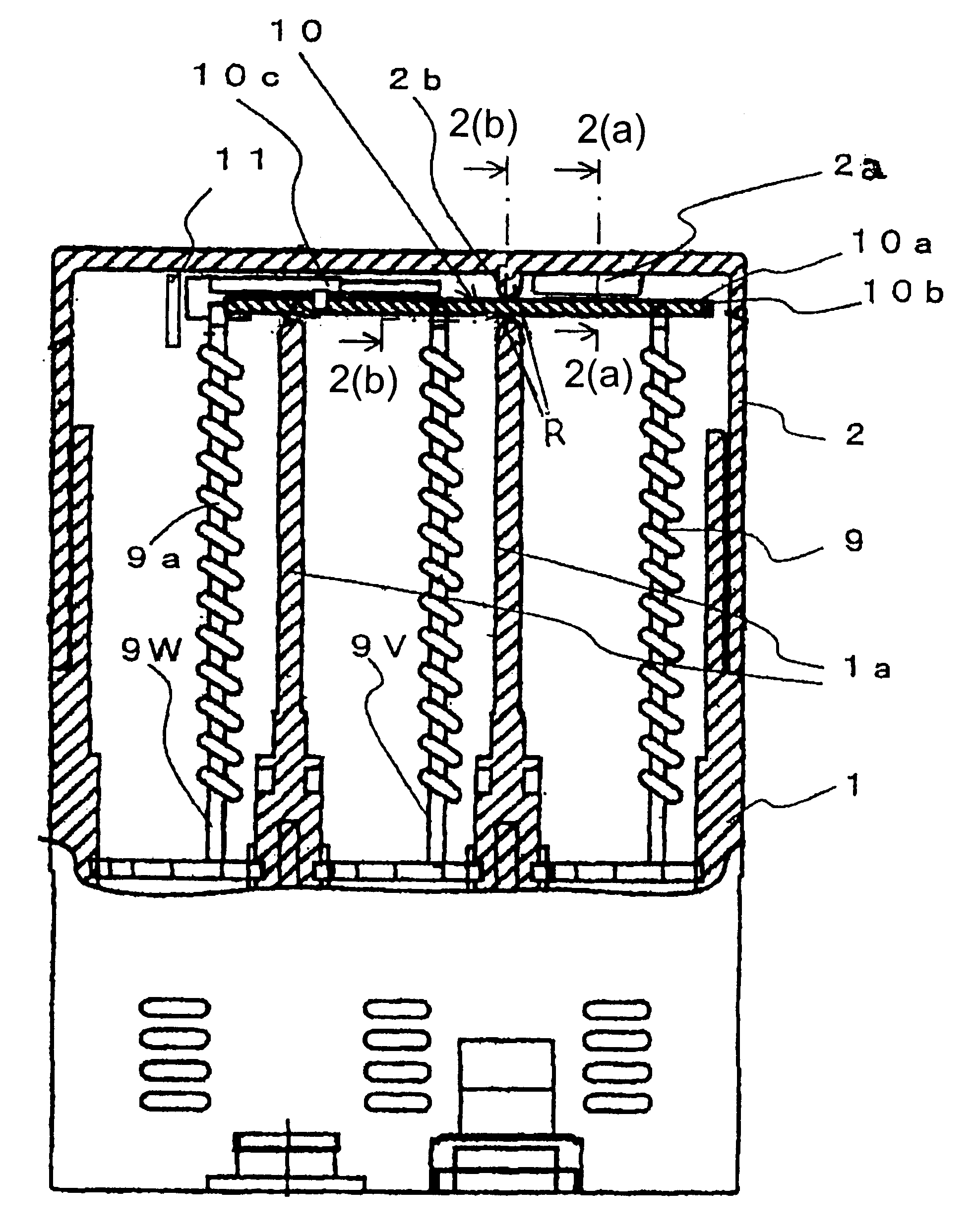
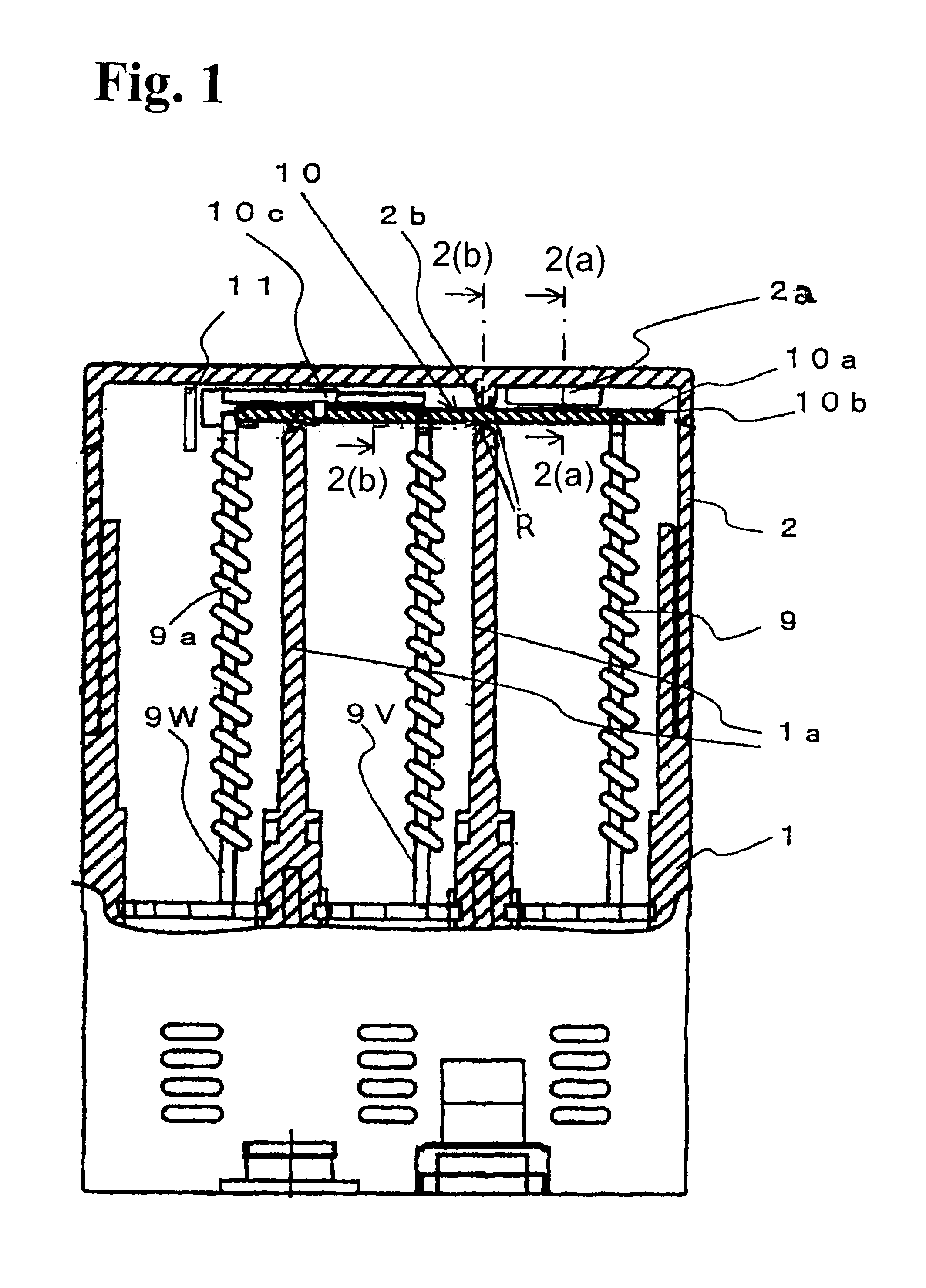
An embodiment of the present invention will be described on the basis of an example shown in FIGS. 1-5. In the figures, as the example, members corresponding to those shown in FIGS. 6, 7(a) and 7(b) are denoted by the same reference numerals, and descriptions thereof are thus omitted.

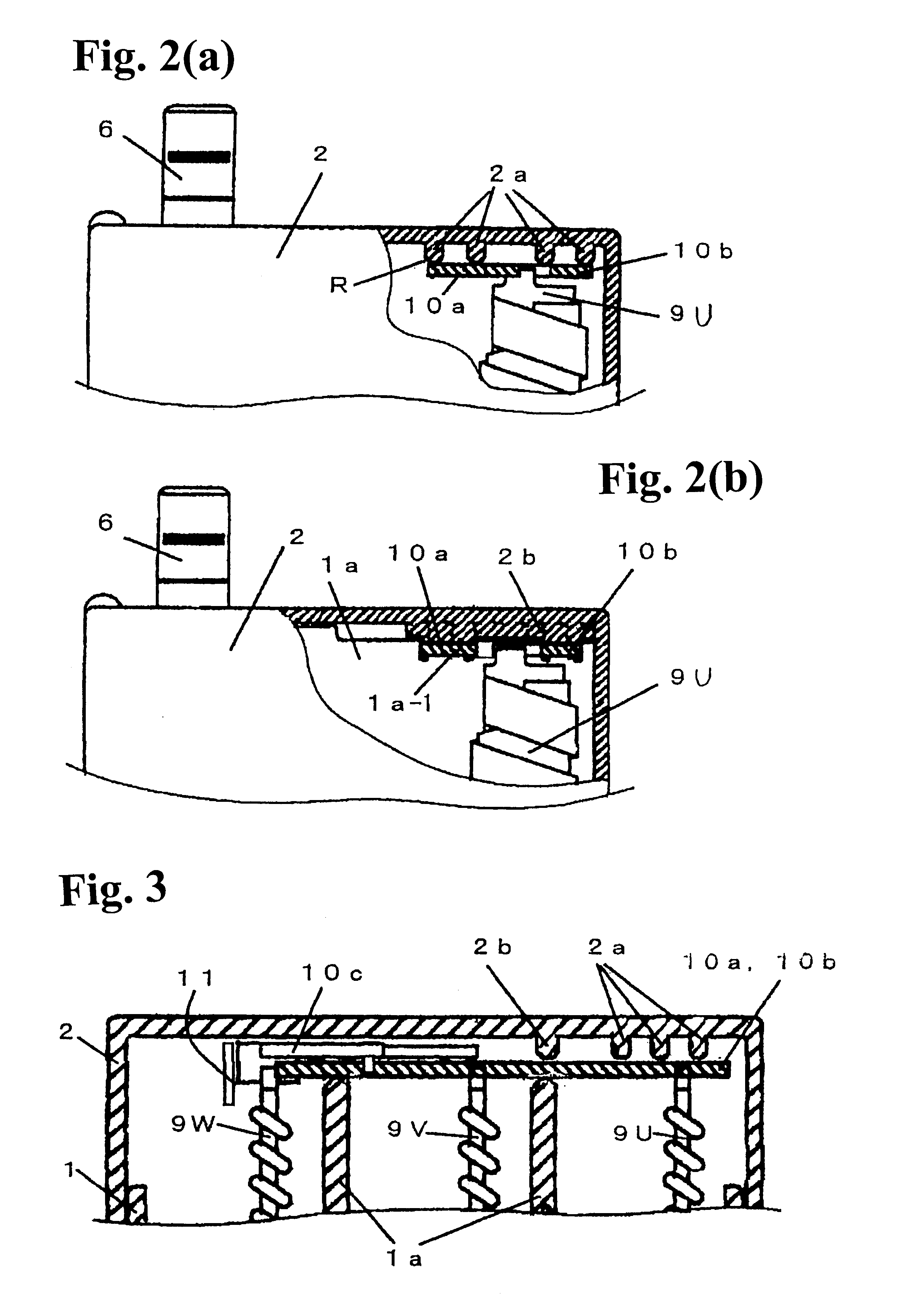
That is, in the illustrated example, a case cover 2 has rib-shaped projections 2a and 2b formed on the inner surface of case cover 2 so as to project therefrom and functioning as position guides for the differential shifter mechanism 10, as compared to the conventional structure shown in FIG. 7. The rib-shaped projections 2a and 2b are integrally molded with the case cover 2, formed of a resin molding.

The rib-shaped projections 2a face the top surfaces of the rear portions (located opposite to the interlocking plate 10c extending over the shifters) of the push shifter 10a and the pull shifter 10b of the differential shifter mechanism 10 and extending along the longitudinal axis thereof. Further, the rib...


PUM


Abstract

A thermal overload open-phase tripping device includes in a case bimetals corresponding to different phases; a differential shifter mechanism composed of a push shifter and a pull shifter, linked to operating ends of the bimetals, and an interlocking plate; and a compensating bimetal for transmitting output from the shifter mechanism to an opening and closing mechanism section of a breaker main body. The push and pull shifters are slidably supported to extend over interphase partition walls in the case, and a case cover is placed and held over the push and pull shifters. Rib-shaped projections projecting from an inner surface of the case cover and facing the top surfaces of the shifters are provided as shifter position guides to constrain inclination of the shifters moving in accordance with bending displacement of the bimetals to hold the shifters horizontally.

Description

BACKGROUND OF THE INVENTION AND RELATED ART STATEMENTThe present invention relates to a circuit breaker incorporating a thermal overload open-phase tripping device used in a molded case circuit breaker applied to an electric-motor feeding circuit or the like.The structure of a conventional circuit breaker, in this example, a molded case circuit breaker, which incorporates a bimetal-type thermal overload open-phase tripping device, is shown in FIGS. 6, 7(a) and 7(b). In these figures, reference numeral 1 denotes a breaker case (resin molding), reference numeral 2 denotes a case cover (resin molding) placed on the case 1, reference numerals 3 and 4 denote load-side main circuit terminals and power-supply-side main circuit terminals, reference numeral 5 denotes an opening and closing mechanism section for a main circuit contact shoe, reference numeral 6 denotes an opening and closing operating handle, reference numeral 7 denotes a bimetal-type thermal overload open-phase tripping devic...

Claims


Application Information

Patent Timeline
Patent Type & Authority Patents(United States)
IPC IPC(8): H01H83/00H01H71/16H01H71/00H01H71/74H01H71/12H01H83/22H01H3/62H01H3/00H01H61/01H01H37/52
CPCH01H83/223H01H71/7445H01H71/161H01H3/62
Inventor KUBOYAMA, KATSUNORIUCHIDA, NAOSHINAGAHIRO, ISAMU
Owner FUJI ELECTRIC FA COMPONENTS & SYST CO LTD
Why Eureka
Try Eureka