Multi-resonant, high-impedance electromagnetic surfaces

a high-impedance, electromagnetic surface technology, applied in the direction of antennas, screened loop antennas, electrical equipment, etc., can solve the problems of harmonic relationship of frequency resonances and hence uncontrollable, the combination of wire antennas/pec surfaces cannot radiate efficiently, and the topic of ongoing research and non-trivial expens

Inactive Publication Date: 2003-01-28
E TENNA CORP
View PDF12 Cites 136 Cited by
  • Summary
  • Abstract
  • Description
  • Claims
  • Application Information

AI Technical Summary

Problems solved by technology

Furthermore, the prior art surface offers a high surface impedance for both x and y components of tangential electric field, which is not possible with a corrugated waveguide.
The wire antenna / PEC surface combination will not radiate efficiently due to a very severe impedance mismatch.
These higher frequency resonances are harmonically related and hence uncontrollable.
Alternatively, magnetic materials could be used to load the spacer layer, but this is a topic of ongoing research and nontrivial expense.

Method used


Image

  • Multi-resonant, high-impedance electromagnetic surfaces
  • Multi-resonant, high-impedance electromagnetic surfaces
  • Multi-resonant, high-impedance electromagnetic surfaces

Examples


Embodiment Construction

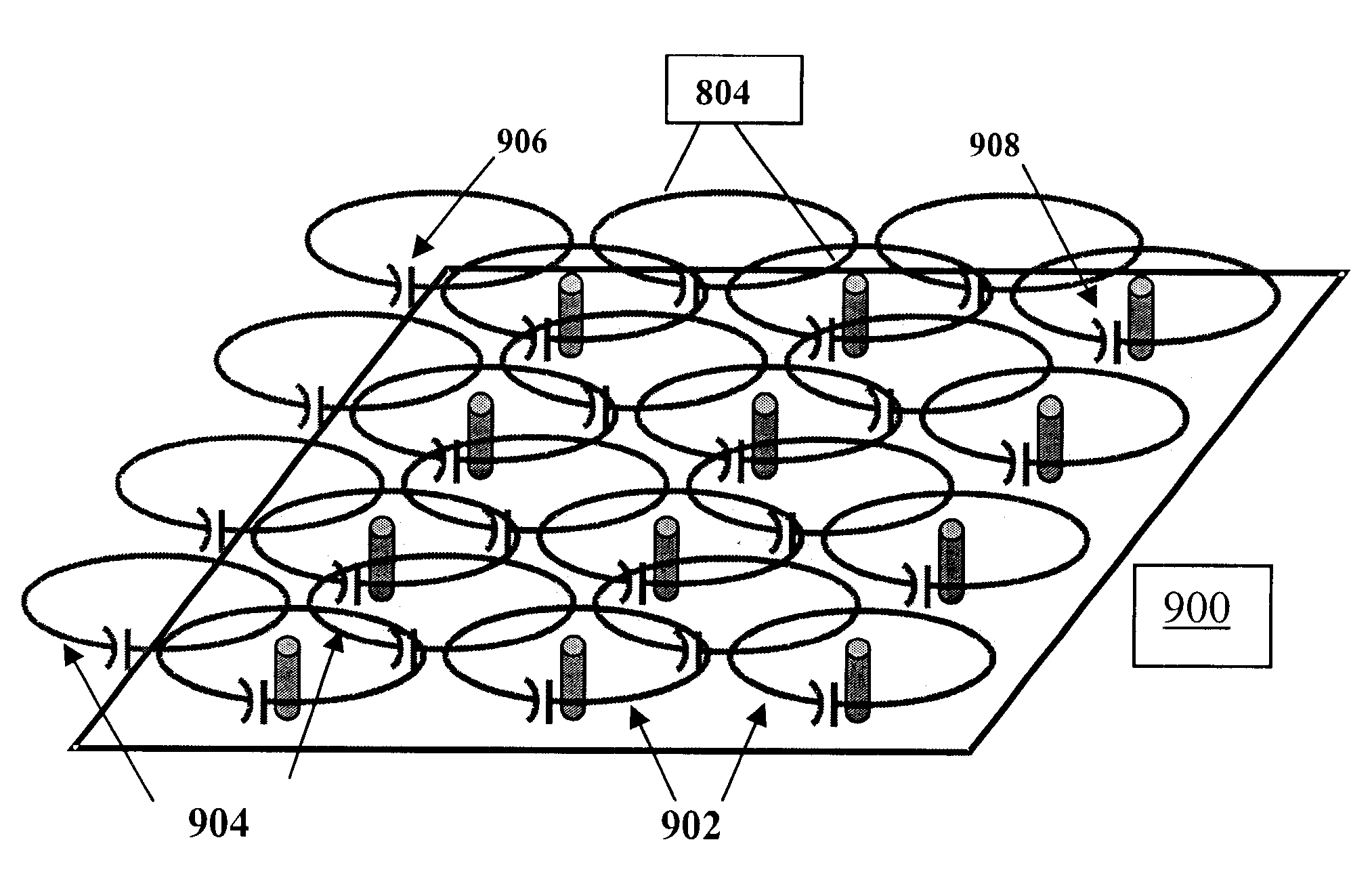
A planar, electrically-thin, anisotropic material is designed to be a high-impedance surface to electromagnetic waves. It is a two-layer, periodic, magnetodielectric structure where each layer is engineered to have a specific tensor permittivity and permeability behavior with frequency. This structure has the properties of an artificial magnetic conductor over a limited frequency band or bands, whereby, near its resonant frequency, the reflection amplitude is near unity and the reflection phase at the surface lies between + / -90 degrees. This engineered material also offers suppression of transverse electric (TE) and transverse magnetic (TM) mode surface waves over a band of frequencies near where it operates as a high impedance surface. The high impedance surface provides substantial improvements and advantages. Advantages include a description of how to optimize the material's effective media constituent parameters to offer multiple bands of high surface impedance. Advantages furth...


PUM


Abstract

An artificial magnetic conductor is resonant at multiple resonance frequencies. The artificial magnetic conductor is characterized by an effective media model which includes a first layer and a second layer. Each layer has a layer tensor permittivity and a layer tensor permeability having non-zero elements on the main tensor diagonal only.

Description

The present invention relates generally to high-impedance surfaces. More particularly, the present invention relates to a multi-resonant, high-impedance electromagnetic surface.A high impedance surface is a lossless, reactive surface whose equivalent surface impedance, ##EQU1##approximates an open circuit and which inhibits the flow of equivalent tangential electric surface current, thereby approximating a zero tangential magnetic field, H.sub.tan.apprxeq.0. E.sub.tan and H.sub.tan are the electric and magnetic fields, respectively, tangential to the surface. High impedance surfaces have been used in various antenna applications. These applications range from corrugated horns which are specially designed to offer equal E and H plane half power beamwidths to traveling wave antennas in planar or cylindrical form. However, in these applications, the corrugations or troughs are made of metal where the depth of the corrugations is one quarter of a free space wavelength, .lambda. / 4, where...

Claims


Application Information

Patent Timeline
Patent Type & Authority Patents(United States)
IPC IPC(8): H01Q15/00H01Q7/00H01Q9/04
CPCH01Q7/00H01Q15/008H01Q9/0442
Inventor DIAZ, RODOLFO E.MCKINZIE, III, WILLIAM E.
Owner E TENNA CORP
Why Eureka
Try Eureka