Recording medium feed path for an image forming apparatus

a technology of image forming apparatus and feed path, which is applied in the direction of electrographic process apparatus, instruments, corona discharge, etc., can solve the problems of poor image transfer and gradual wear of the ribs, and achieve the effect of facilitating the maintenance of the image forming apparatus

Inactive Publication Date: 2003-01-28
BROTHER KOGYO KK
View PDF1 Cites 23 Cited by
  • Summary
  • Abstract
  • Description
  • Claims
  • Application Information

AI Technical Summary

Benefits of technology

An image forming apparatus according to the invention may include a roller rotatably provided upstream of a transfer roller in a feeding direction of a recording medium. The roller guides the recording medium between a photosensitive drum and the transfer roller. As the roller is rotatably provided, friction between the recording medium and the roller may be reduced. Accordingly, wear or abrasion of the roller may be reduced. With the wear or abrasion of the roller reduced, a gap may not be formed between the photosensitive drum and the recording medium, so that electric discharge at the gap can be prevented.
All of the photosensitive drum, the transfer roller, and the roller can be provided in a process unit. It is preferable that the process unit is detachably set in the image forming apparatus. By structuring the process unit so as to be detachably mounted on the image forming apparatus, the maintenance of the image forming apparatus is facilitated.

Problems solved by technology

This makes the rib gradually wear down during a long period of usage of the laser printer.
When the electric discharge occurs at the gap due to the voltage applied to the transfer roller, poor image transfer is brought about.

Method used


Image

  • Recording medium feed path for an image forming apparatus
  • Recording medium feed path for an image forming apparatus
  • Recording medium feed path for an image forming apparatus

Examples


Embodiment Construction

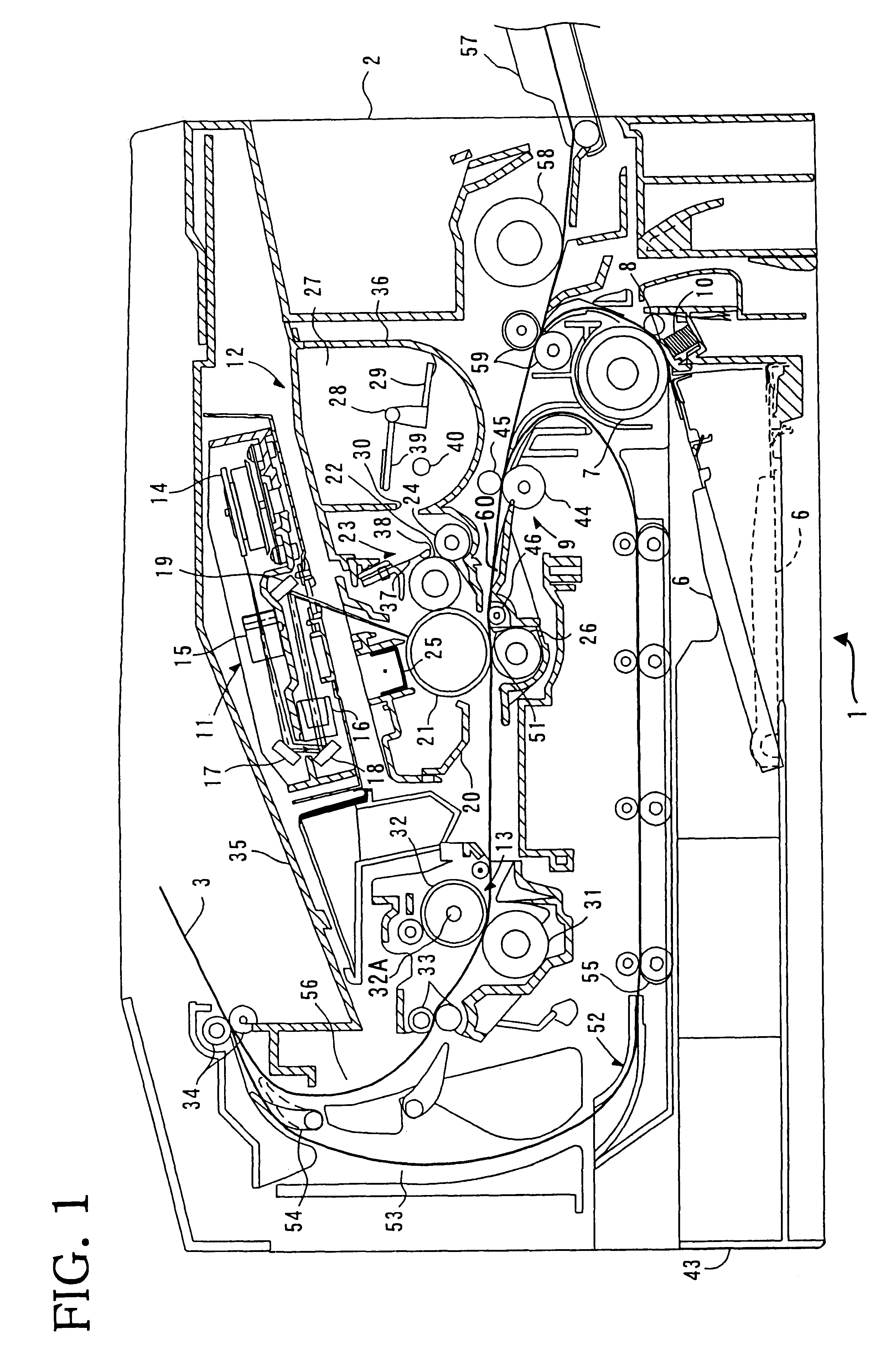
An exemplary embodiment of the invention will be described in detail with reference to the figures.

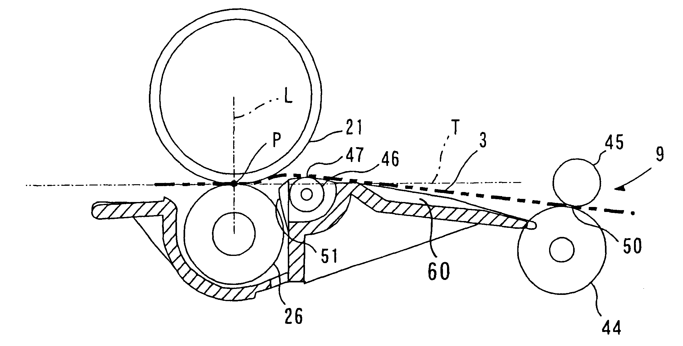
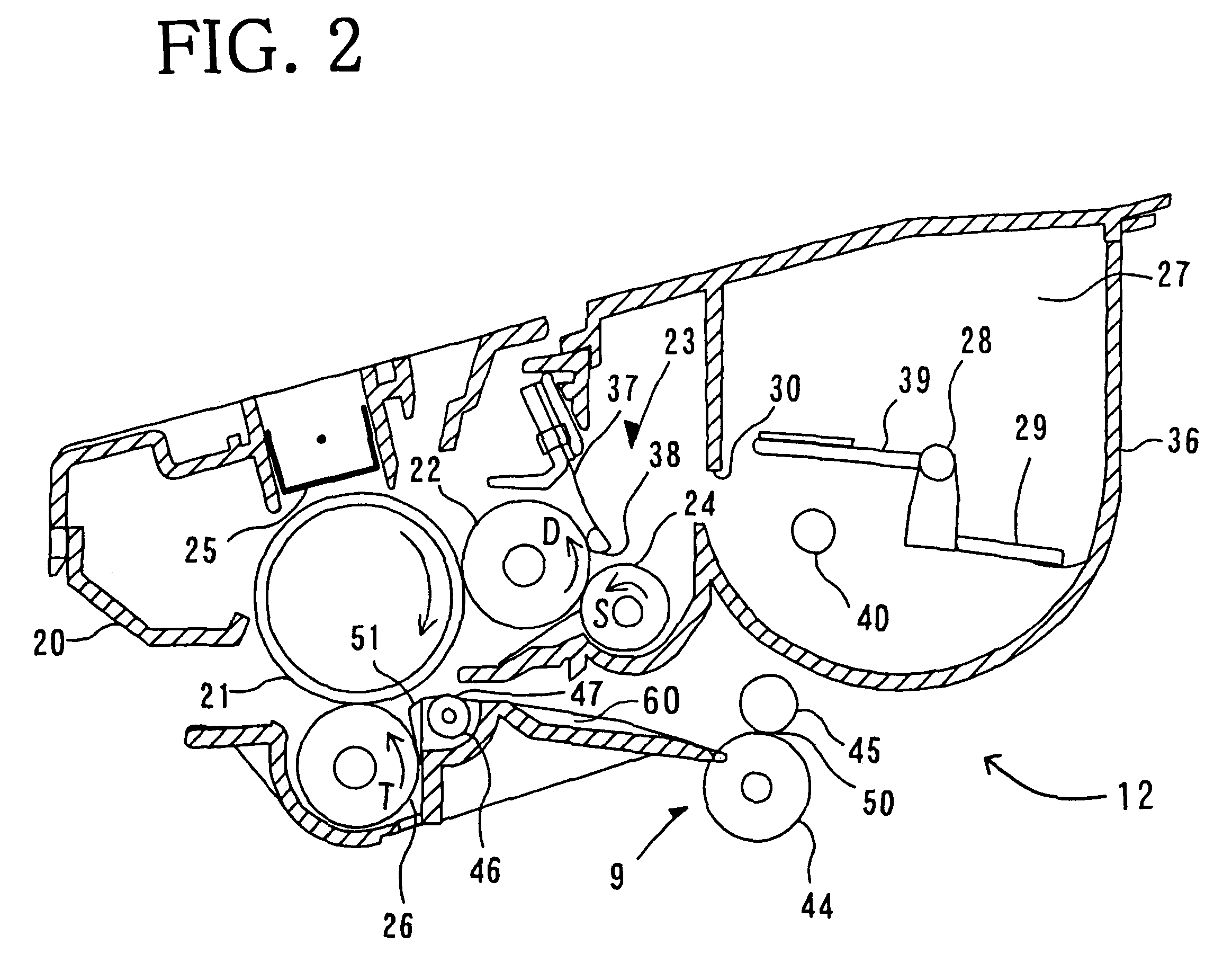
Referring to FIG. 1, configuration of a laser printer 1 will be described below. As shown in FIG. 1, the laser printer 1 is provided with a paper tray 43 at the bottom of a main casing 2. The paper tray 43 is detachably set in the casing 2. Provided in the paper tray 43 is a paper pressure plate 6 that presses paper sheets 3 set in the paper tray 43 upwardly. Disposed at one upper end of the paper tray 43 are a pick-up roller 7 and a separation pad 8. First paper supply rollers 59 are disposed downstream of the pick-up roller 7 in a feeding direction of the paper sheet 3. Register rollers 9 are disposed downstream of the first paper supply rollers 59 in the feeding direction of the paper sheet 3.

The paper pressure plate 6 supports a stack of the paper sheets 3. The paper pressure plate 6 pivots on one end far from the pick-up roller 7, so that the other end of the paper pressure plate ...


PUM


Abstract

An image forming apparatus includes a photosensitive drum and a transfer roller disposed opposite to the photosensitive drum. Provided upstream of the transfer roller in a paper sheet feeding direction is a roller that guides a paper sheet between the photosensitive drum and the transfer roller. The roller is disposed at such a position that the paper sheet is brought into a surface of the photosensitive drum and then supplied between the photosensitive drum and the transfer roller. With the above-described structure, a gap is not formed between the paper sheet and the photosensitive drum, so that poor image transfer attributable to an electric discharge, that occurs at the gap, can be prevented.

Description

BACKGROUND OF THE INVENTION1. Field of InventionThe invention relates to an image forming apparatus, such as a laser printer, that forms an image in an electrophotographic method and to a process unit removably set in the image forming apparatus.2. Description of Related ArtA laser printer forms an image onto a sheet of paper in an electrophotographic method. More specifically, the laser printer includes a photosensitive drum, a charger, a scanner unit, a developing roller, and a transfer roller. As the photosensitive drum rotates, a surface of the photosensitive drum is uniformly charged by the charger. The scanner unit emits a laser beam based on image data. The laser beam scans across the charged surface of the photosensitive drum at high speed. Then, an electrostatic latent image is formed on the surface of the photosensitive drum. Toner carried on the developing roller is supplied to the electrostatic latent image, thereby developing the electrostatic latent image into a visibl...

Claims


Application Information

Patent Timeline
Patent Type & Authority Patents(United States)
IPC IPC(8): G03G15/16G03G21/18G03G15/08G03G15/00
CPCG03G15/167G03G21/1814G03G2221/1642
Inventor SATO, FUMIKAZUISHIKAWA, SATORU
Owner BROTHER KOGYO KK
Why Eureka
Try Eureka