Electronic device support and method

a technology for electronic devices and supports, applied in the direction of electrical equipment casings/cabinets/drawers, furniture parts, instruments, etc., can solve the problems of time-consuming placement of supports within the standard racks, difficulty in removing modules from the racks, and protracted installation and maintenance of commercial computer systems. , to achieve the effect of improving the ease, improving the placement, and improving the service and maintenance of electronic devices

Inactive Publication Date: 2003-02-04
SILICON GRAPHICS INT CORP +1
View PDF49 Cites 75 Cited by
  • Summary
  • Abstract
  • Description
  • Claims
  • Application Information

AI Technical Summary

Benefits of technology

The resulting support bracket improves the ease with which the support bracket is installed, repositioned or removed from a structure and improves placement, installation, service and upgrade of electronic devices.

Problems solved by technology

Installation, service and upgrade of a commercial computer system can be a protracted and cumbersome process.
Installation may require time consuming placement of supports within the standard racks.
The difficulty of removing a module from the rack can be compounded by the increased weight of the element.
Modules are typically difficult to align and install into the rack.
Modules will typically be positioned within racks providing poor access to the module.
This can slow the installation, service, and upgrade processes making larger systems from these components less desirable.
This is also one cause of poor field serviceability.
Proper positioning and servicing of modules is often either not done, poorly done, or is improperly done.

Method used


Image

  • Electronic device support and method
  • Electronic device support and method
  • Electronic device support and method

Examples


Embodiment Construction

In the following detailed description of the preferred embodiments, reference is made to the accompanying drawings that form a part hereof, and in which is shown by way of illustration specific embodiments in which the invention may be practiced. It is to be understood that other embodiments may be utilized and structural changes may be made without departing from the scope of the present invention.

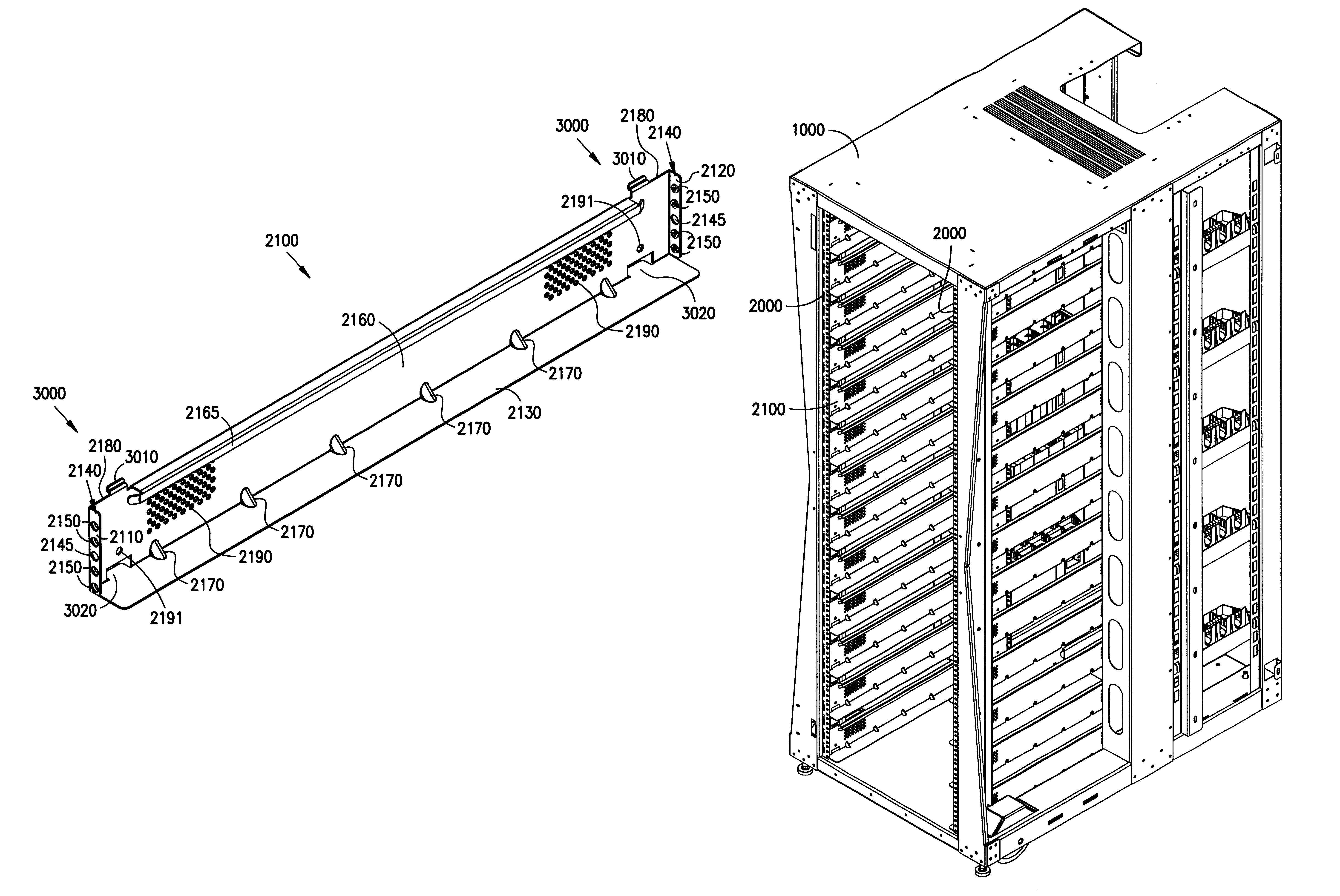
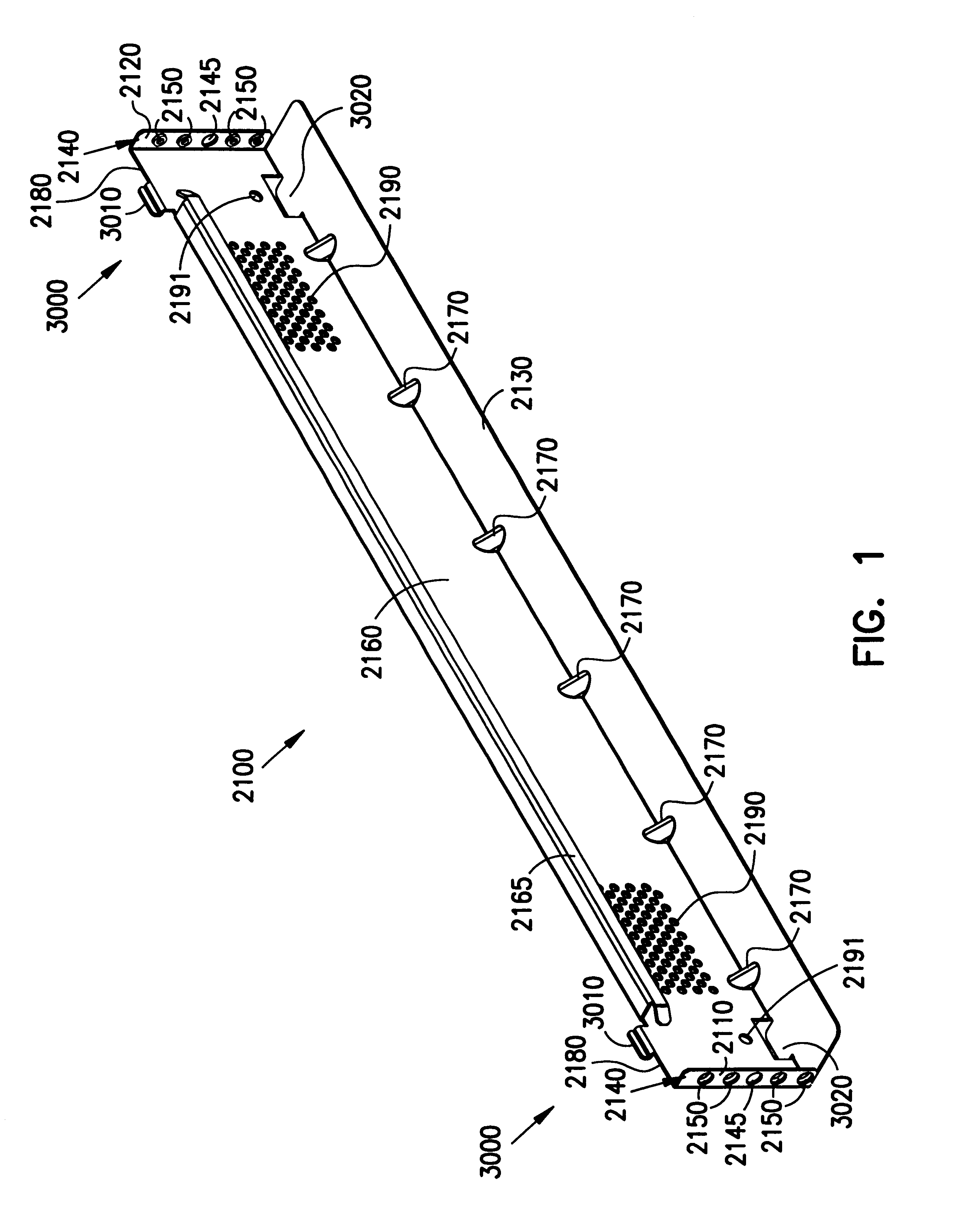
FIG. 1 illustrates an improved support bracket 2100 for use in mounting electronic devices in a structure. The improved support bracket 2100 provides improved adjustability in that the support bracket 2100 can be vertically adjusted along the length of the structure with greater ease than conventional supports. In one embodiment, the support bracket 2100 includes a front mounting portion 2110 and rear mounting portion 2120 including a series of holes 2140 and a support portion 2130 being coupled between the front 2110 and rear 2120 mounting portion. The support can be used to mount an ele...


PUM


Abstract

An improved support bracket for supporting electronic devices provides improved adjustability and alignment. The support bracket includes a front surface and a rear surface each including a portion having at least one threaded hole and a support portion between the front surface and rear surface for supporting an electronic device. The support bracket includes a side portion having a mechanism for coupling the side portion to a structure, a guide portion and a support portion for supporting an electronic device.

Description

This invention relates to hardware for electronic devices, and in particular to a support for supporting electronic devices.Commercial use electronic systems typically include electronic devices resting on a special sub-floor allowing for cable routing and grounding beneath the floor surface. In some cases, electronic devices are supported in commercial structures or racks.Installation, service and upgrade of a commercial computer system can be a protracted and cumbersome process. Installation may require time consuming placement of supports within the standard racks.Service and upgrade of commercial systems also typically requires removal of an electronic device from the rack. The difficulty of removing a module from the rack can be compounded by the increased weight of the element. Service and upgrade also may require disassembly of the computer module housing to access, repair or replace components internal to the module before the module is replaced within a rack.When an electro...

Claims


Application Information

Patent Timeline
Patent Type & Authority Patents(United States)
IPC IPC(8): G02B6/44
CPCG02B6/4471G02B6/4452
Inventor FRANZ, PERRY D.GLANZMAN, JEFFREY MARK
Owner SILICON GRAPHICS INT CORP
Why Eureka
Try Eureka