Lever lock unit

a technology of lever lock and lock body, which is applied in the direction of cylinder locks, tumbler locks, keys, etc., can solve the problems of wear marks on the key and lever tumbler in the passage of time, the multi-key/tumbler system cannot be readily implemented in some lock units of this kind, and the drawback of key and lever tumbler wear marks

Inactive Publication Date: 2003-02-18
FAS LASFAB
View PDF12 Cites 16 Cited by
  • Summary
  • Abstract
  • Description
  • Claims
  • Application Information

AI Technical Summary

Benefits of technology

One object of the present invention is to provide a lever lock unit which

Problems solved by technology

One of these drawbacks is that turning of the key results in wear between key and lever tumblers, which results in wear marks on both key and lever tumblers in the passage of time.
Another drawback is that a multi-key/tu

Method used


Image

  • Lever lock unit
  • Lever lock unit
  • Lever lock unit

Examples


Embodiment Construction

that Includes a Latch Pin

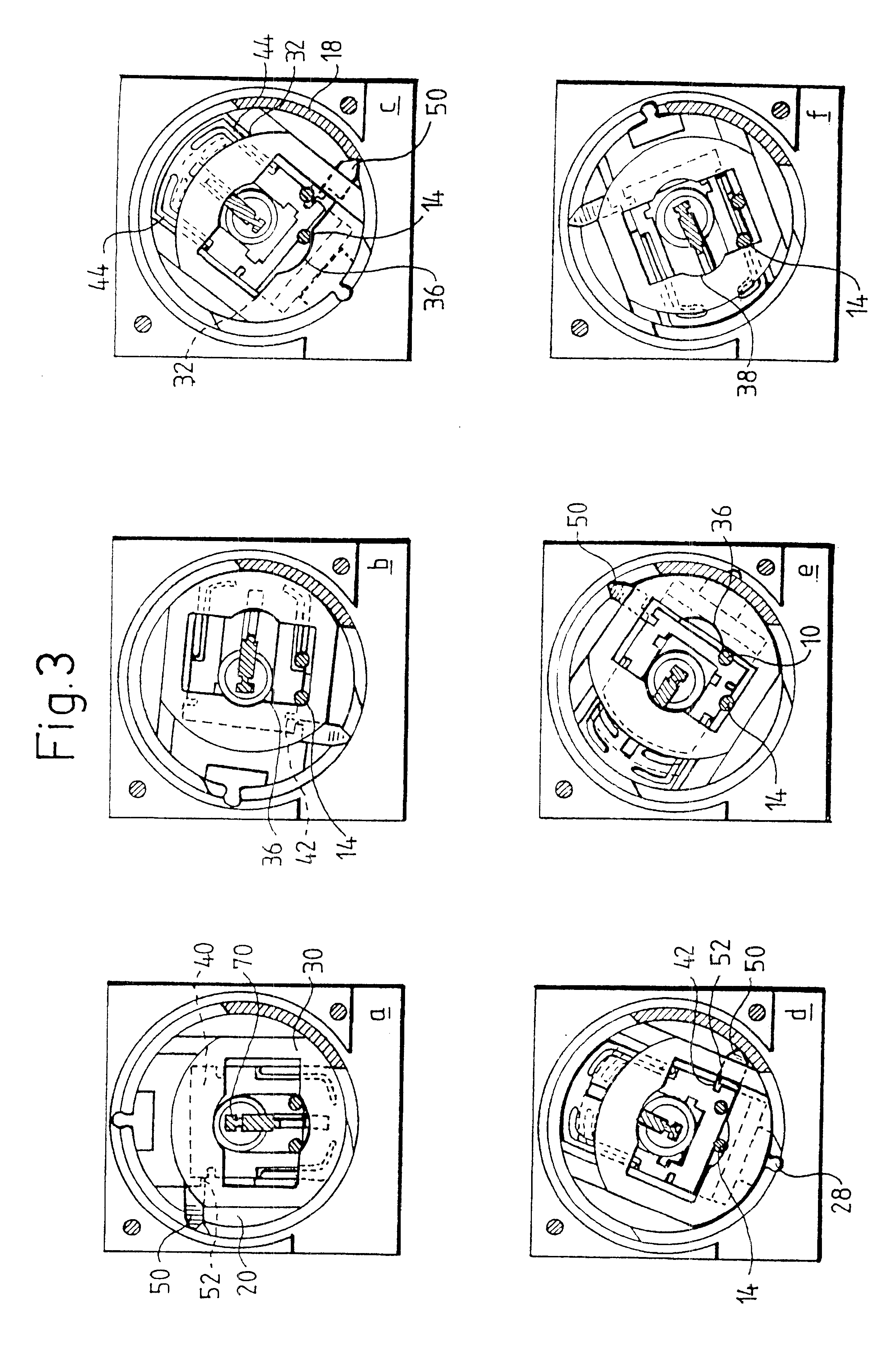
The lock of the aforedescribed embodiment has a given level of security, i.e. the code grooves on the key bit determine whether or not the drum can be rotated. With the intention of providing greater security, there is proposed a further preferred embodiment in which the lock unit also includes latch pins that are intended to block movement of the lever tumblers 40 when a wrong key is inserted into the lock.

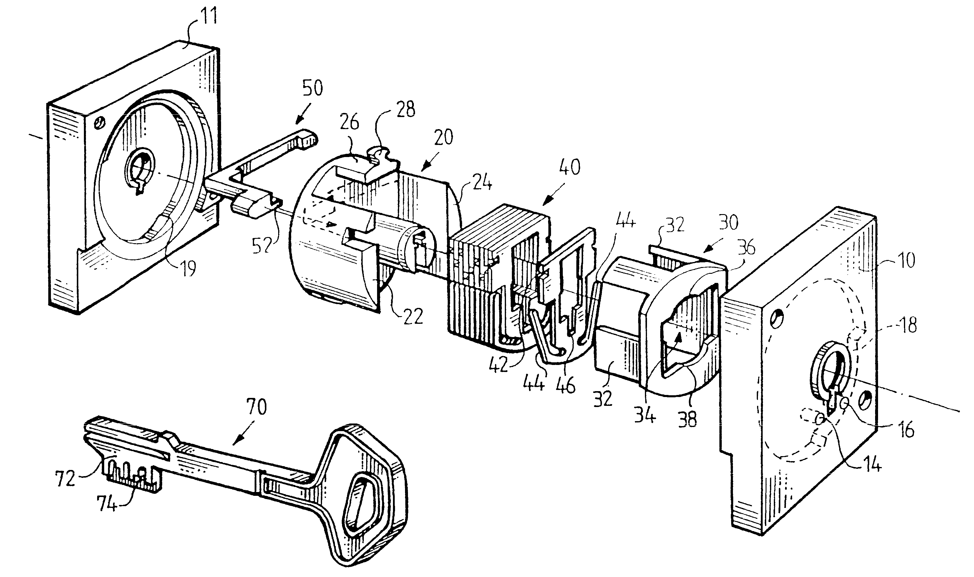
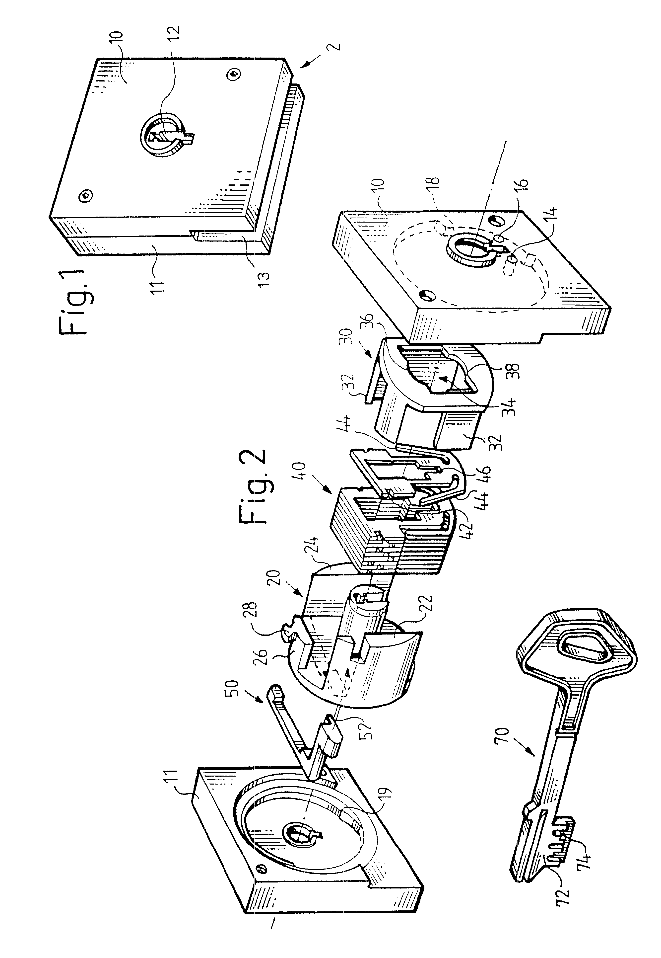
FIG. 5, which corresponds to FIG. 2 illustrating the first embodiment, shows the further embodiment that includes latch pins, wherein those components of the FIG. 2 embodiment that find correspondence in the FIG. 5 embodiment have been identified by the same reference numerals to which a prime has been added.

It will be evident from FIG. 5 that a plurality of latch pins 60 are linearly mounted in the drum 20' for linear movement transversely to the direction of movement of the lever tumblers 40'. The lever tumblers include a recess or notch 48 in the side ...


PUM


Abstract

A lever lock unit includes a housing, a dogging element adapted to actuate a lock bolt, a plurality of lever tumblers that are actuable via the dogging element and movable relative thereto, and a blocking element for blocking movement of the dogging element in the absence of a key or when the wrong key is inserted in the unit. The unit is characterized by a cradle accommodated in the dogging element and adapted to receive the lever tumblers. The dogging element is rotatable and is adapted so that when rotated, the cradle accommodated in the dogging element, and there with also the lever tumblers accomodated in the cradle, will be caused to move linearly in relation to the dogging element and in relation to a key inserted into the unit, for movement of the lever tumblers to a blocking element release position when the correct key is inserted.

Description

The present invention relates to a lever lock unit, and more particularly to a lever lock unit in which movement of the lever tumblers is such as to make forcing and manipulation: of the lock difficult to achieve.The invention also relates to a key for use with such a lock.Known lever locks are constructed so that when turning the lock key, the key seeks for the lever tumblers in order to move the levers to a lock-release position in accordance with a code on the key. This general principle, whereby the key seeks and actuates the lever tumblers as the key is turned is beset with many draw-backs.One of these drawbacks is that turning of the key results in wear between key and lever tumblers, which results in wear marks on both key and lever tumblers in the passage of time. These marks can facilitate manipulation and forcing of the lock.Another drawback is that a multi-key / tumbler system cannot be readily implemented in some lock units of this kind, due to the particular design of the...

Claims


Application Information

Patent Timeline
IPC IPC(8): E05B21/06E05B21/00E05B25/00E05B25/02E05B29/04
CPCE05B21/063Y10T70/7932Y10T70/7616Y10T70/7881Y10T70/7599
Inventor HIRVI, JORMA
Owner FAS LASFAB
Why Eureka
Try Eureka