Method and device for shaping the injection pressure in a fuel injector

a fuel injector and injection pressure technology, which is applied in the direction of fuel injection apparatus, machine/engine, feed system, etc., can solve the problems of affecting the injection quantity, the opening pressure of the inner, and the series tolerances with regard to the manufacturable tolerances are particularly negative,

Inactive Publication Date: 2005-11-17
ROBERT BOSCH GMBH
View PDF7 Cites 16 Cited by
  • Summary
  • Abstract
  • Description
  • Claims
  • Application Information

AI Technical Summary

Benefits of technology

[0015] The fuel injectors actuated by means of the proposed triggering method are advantageously designed so that they have a pronounced pressure maximum at the beginning of the main injection phase. This makes it possible for the maximum occurring injection pressure to be influenced in a particularly favorable way by means of a multiple triggering of the control valve, which can be embodied, for example, in the form of a solenoid valve and actuates a servo valve of a fuel injector, thus permitting an early activation of the second, inner needle part of a multipart injection valve member.
[0016] The triggering method proposed according to the present invention advantageously uses a servo valve as the on / off valve since its servo valve piston has a virtually linear opening and closing motion. Furthermore, in an on / off valve embodied in the form of a servo valve, the opening and closing speed of a valve piston can be ideally adapted to the requirements. The control valve that actuates the on / off valve embodied in the form of a servo valve always passes through the complete stroke range in the course of its multiple activation, which assures that the control valve is always operated outside the tolerance-sensitive ballistic range, i.e. between its stops.
[0017] The influencing of the injection pressure curve through multiple triggering of the actuation valve, which is embodied for example in the form of a control valve that actuates a servo valve, can also be used in a fuel injector that has a one-part injection valve member in order to optimally adapt the injection pressure curve to various operating states of the internal combustion engine. As a result, the injection pressure curve of the engine can be adapted to characteristic curve requirements without the need for modifications to the model-related basic designs of the fuel injectors used in the internal combustion engine.

Problems solved by technology

An uncontrolled opening of the second, inner needle part of a multipart injection valve member leads to an abrupt jump in the injection quantity.
Manufacture-conditional series tolerances with regard to the manufacturable tolerances therefore have a particularly negative effect with regard to the fuel supplied to the combustion chamber of an autoignition internal combustion engine.
With regard to the pressure fluctuations occurring in a common rail of the fuel injection system, therefore, the opening pressure of the inner, second needle part of a multipart injection valve member is very problematic.

Method used


Image

  • Method and device for shaping the injection pressure in a fuel injector
  • Method and device for shaping the injection pressure in a fuel injector
  • Method and device for shaping the injection pressure in a fuel injector

Examples


Embodiment Construction

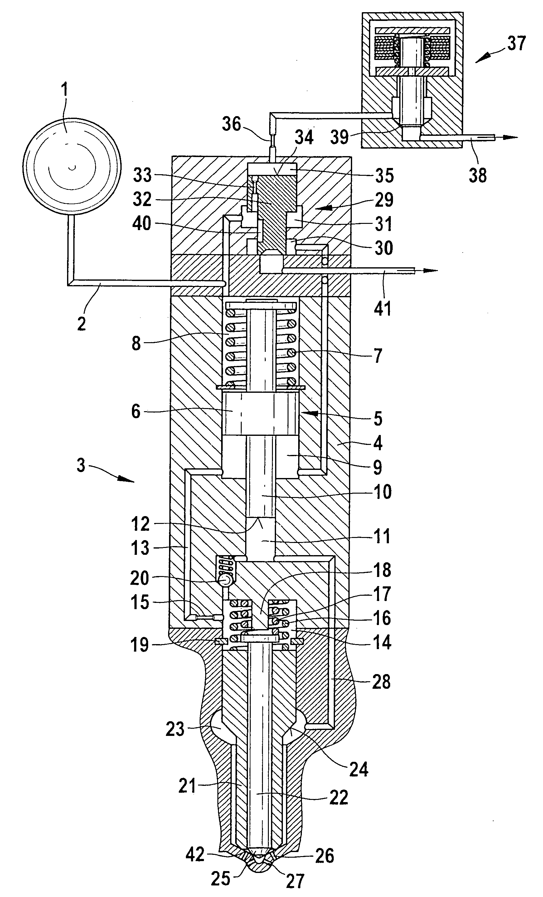
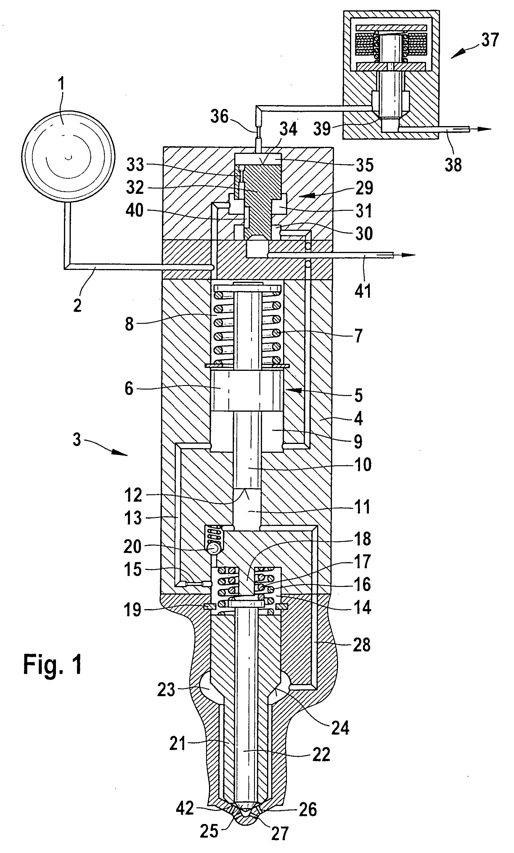
[0025]FIG. 1 shows a hydraulic circuit diagram of a fuel injector that can be triggered using the triggering method proposed according to the present invention. A common rail 1 is connected to a high-pressure line 2 and a fuel injector 3. The fuel injector 3 has an injector body 4, which has a multipart design to facilitate installation of the individual components. The injector body 4 contains a pressure booster 5. The pressure booster 5 has a first pressure booster piston part 6 and a second pressure booster piston part 10. The first pressure booster piston part 6 separates a working chamber 8 from a differential pressure chamber 9 of the pressure booster 5. The working chamber 8 contains a return spring 7. The high-pressure line 2 acts on the working chamber 8 of the pressure booster 5 with highly pressurized fuel. The pressure level exerted on the working chamber 8 of the pressure booster 5 depends on the pressure level prevailing in the common rail 1 (system pressure).

[0026] T...


PUM


Abstract

A method for triggering a fuel injector via an on/off valve and a control valve that actuates it. The fuel injector has a pressure booster whose piston parts separate a working chamber from a differential pressure chamber. Via a compression chamber of the pressure booster, a nozzle chamber of the fuel injector can be acted on with highly pressurized fuel. The working chamber of the pressure booster communicates continuously with a common rail. During the main phase in which fuel is injected into the combustion chamber of an internal combustion engine, the control valve that actuates the on/off valve is triggered once or multiple times so that the maximum pressure level occurring at the combustion chamber end of a one-part or multipart injection valve member falls below the maximum achievable pressure level.

Description

[0001] This application is based on German Patent Application 10 2004 022 267.3 filed May 6, 2004, upon which priority is claimed. BACKGROUND OF THE INVENTION [0002] 1. Field of the Invention [0003] It is possible to use both pressure-controlled and stroke-controlled injection systems to supply fuel to combustion chambers of autoignition internal combustion engines. In addition to unit fuel injectors, these fuel injection systems are also embodied in the form of unit pumps and accumulator (common rail) injection systems. Common rail injection systems, for example, advantageously permit the injection pressure to be adapted to the load and engine speed. It is generally necessary to achieve the highest injection pressure possible in order to achieve high specific loads and reduce engine emissions. [0004] 2. Description of the Prior Art [0005] DE 101 23 910.6 relates to a fuel injection system that is used in an internal combustion engine. Fuel injectors supply fuel to the combustion ch...

Claims


Application Information

Patent Timeline
Patent Type & Authority Applications(United States)
IPC IPC(8): F02M45/08F02M45/12F02M47/02F02M57/02F02M59/46F02M61/16F02M63/02
CPCF02M45/086F02M45/12F02M47/027F02M2200/46F02M61/161F02M63/0049F02M63/0225F02M57/025
Inventor MAGEL, HANS-CHRISTOPH
Owner ROBERT BOSCH GMBH
Why Eureka
Try Eureka