

Driving unit that comprises a hydraulic motor and a reduction gear
a technology of hydraulic motor and reduction gear, which is applied in the direction of fluid gearing, coupling, gearing, etc., can solve the problems that the conventional type of driving unit is all being demanded to be further downsized
- Summary
- Abstract
- Description
- Claims
- Application Information
AI Technical Summary
Problems solved by technology
Method used
Image

Examples
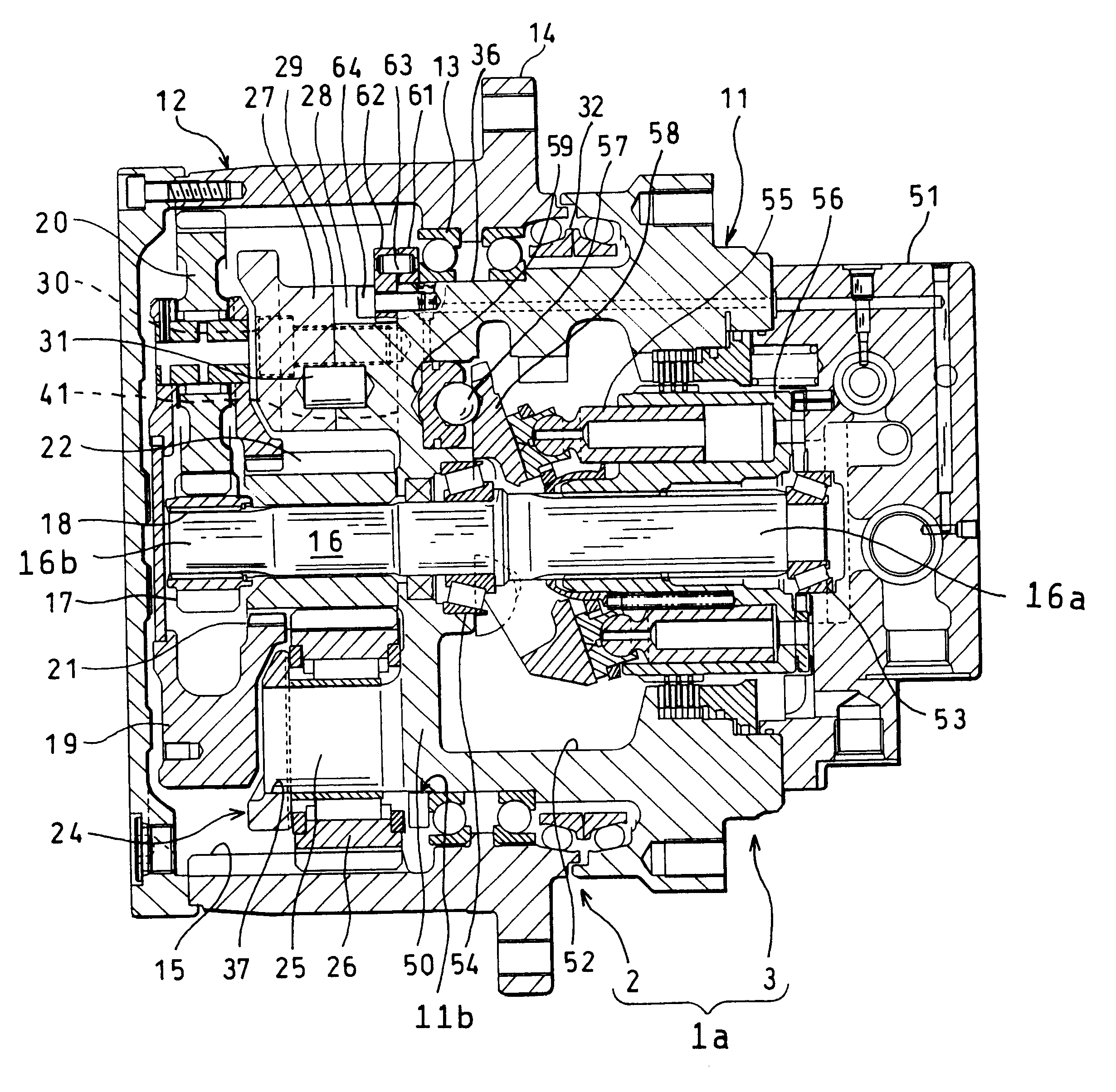
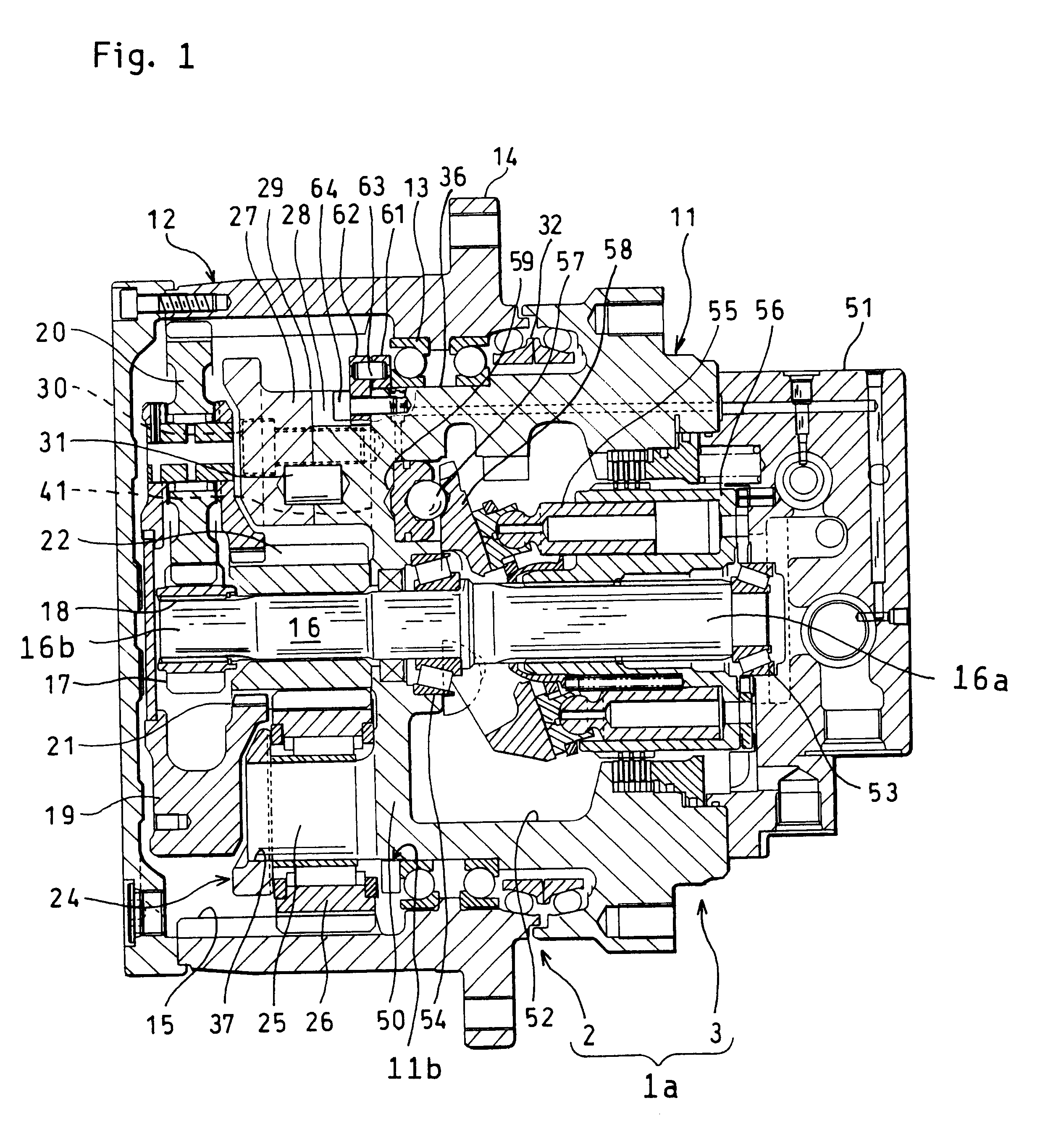
first embodiment
The example of the invention as described above may be modified as follows, for practical use of the invention.
(1) While the reduction gear mechanism 2 having the two-stage planetary gear train was illustrated, the supporting structure of the embodiment of the present invention can be applied to a three-stage planetary gear train as well by the application to the final stage planetary gear train.
(2) The planetary gears revolving around the sun gear of the planetary gear train is not limited in number to three. For example, for four planetary gears, the supporting structure of the embodiment of the present invention can be applied thereto by increasing the trunnion bosses and the support pillars in number to four.
(3) In FIGS. 12 and 13, the spline 18 is not limited to the straight spline extending in parallel to the axis of the rotating shaft. The spline formed to extend obliquely with respect to the axial direction may be used.
second embodiment
(An Example of Second Embodiment)
Then, an example of the second embodiment of the present invention will be described below. To avoid repetition of description of corresponding construction to that of the example of the first embodiment, like numerals are labeled to corresponding parts throughout the drawings. FIG. 14 is a sectional view of the driving unit 1b according to an example of the second embodiment. The driving unit 1b of the example of the second embodiment is different from the driving unit 1a of the example of the first embodiment shown in FIG. 1 in the following points.
1 Rather than being integrally projected from the bottom 50 of the fixed casing 11, a trunnion boss 75 is formed as a single part and journaled at its opposite ends between the bottom 50 of the fixed casing 11 and the holder 24;
2 The crowned portion is formed in the engaging cog 17c of the first. sun gear 17, rather than being formed in the spline cog 18a of the rotating shaft 16 as in the example of the...
PUM
 Abstract
Description
Claims
Application Information