Method and system for producing sputtered thin films with sub-angstrom thickness uniformity or custom thickness gradients

a thin film, uniform thickness technology, applied in the direction of instruments, optical elements, vacuum evaporation coating, etc., can solve the problems of not being suitable for a substrate, radial non-uniform thickness of coating, and requiring tedious iteration of masking operation

Inactive Publication Date: 2003-02-25
EUV
View PDF3 Cites 24 Cited by
  • Summary
  • Abstract
  • Description
  • Claims
  • Application Information

AI Technical Summary

Problems solved by technology

However, radial non-uniformities in coating thickness typically result.
However, such a masking operation requires tedious iteration to determine the optimal shape of each mask, and can be impractical for cases in which very high uniformity is required.
Also, a mask is not suitable for a substrate whose center must be coated, since the mask cannot be perfectly positioned at the center of rotation of a spinning substrate, and thus a small spot at the center of the masked substrate will be coated with the wrong thickness.
However, use of baffles prevents independent deposition of different coating distributions on two substrates, each of which sweeps sequentially across a source during a single platter rotation.
However, the trial and error empirical approach to optimizing the platter velocity function (platter velocity as a function of time) in an effort to achieve a desired radial variation in coating thickness (e.g., an acceptably uniform thickness) has proved to be incapable of achieving adequate uniformity on acceptably small substrates for some applications (e.g., the 0.1%, or better, uniformity needed for EUV lithography) without use of baffles or masks.
The inventors have recognized that slow spin speeds for the substrate (while the substrate is swept across the source) give rise to a ripple effect (rapid oscillation of coating thickness as a function of radius across the substrate), which may or may not be acceptable for specific applications.

Method used


Image

  • Method and system for producing sputtered thin films with sub-angstrom thickness uniformity or custom thickness gradients
  • Method and system for producing sputtered thin films with sub-angstrom thickness uniformity or custom thickness gradients
  • Method and system for producing sputtered thin films with sub-angstrom thickness uniformity or custom thickness gradients

Examples


Embodiment Construction

The invention pertains to methods and systems for vapor deposition (such as sputtering, CVD, and electron beam evaporation methods and systems) in which a substrate to be coated is passed through a vapor of the coating material and accumulates a film (typically a very thin film) of the coating material through condensation of the vapor.

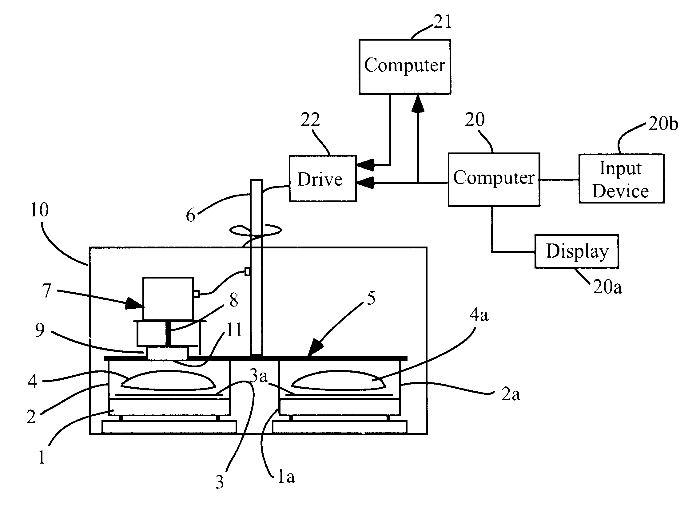
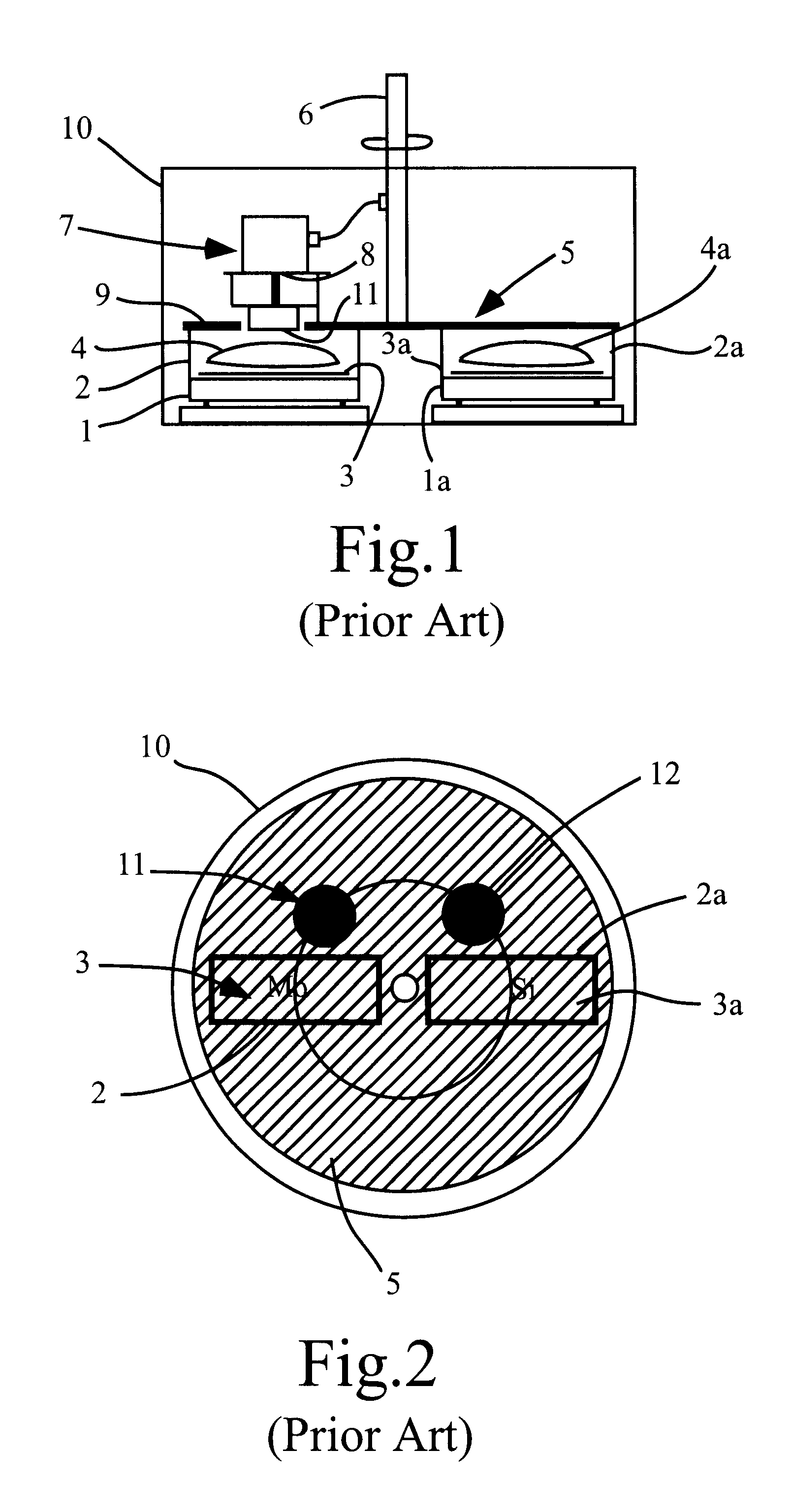
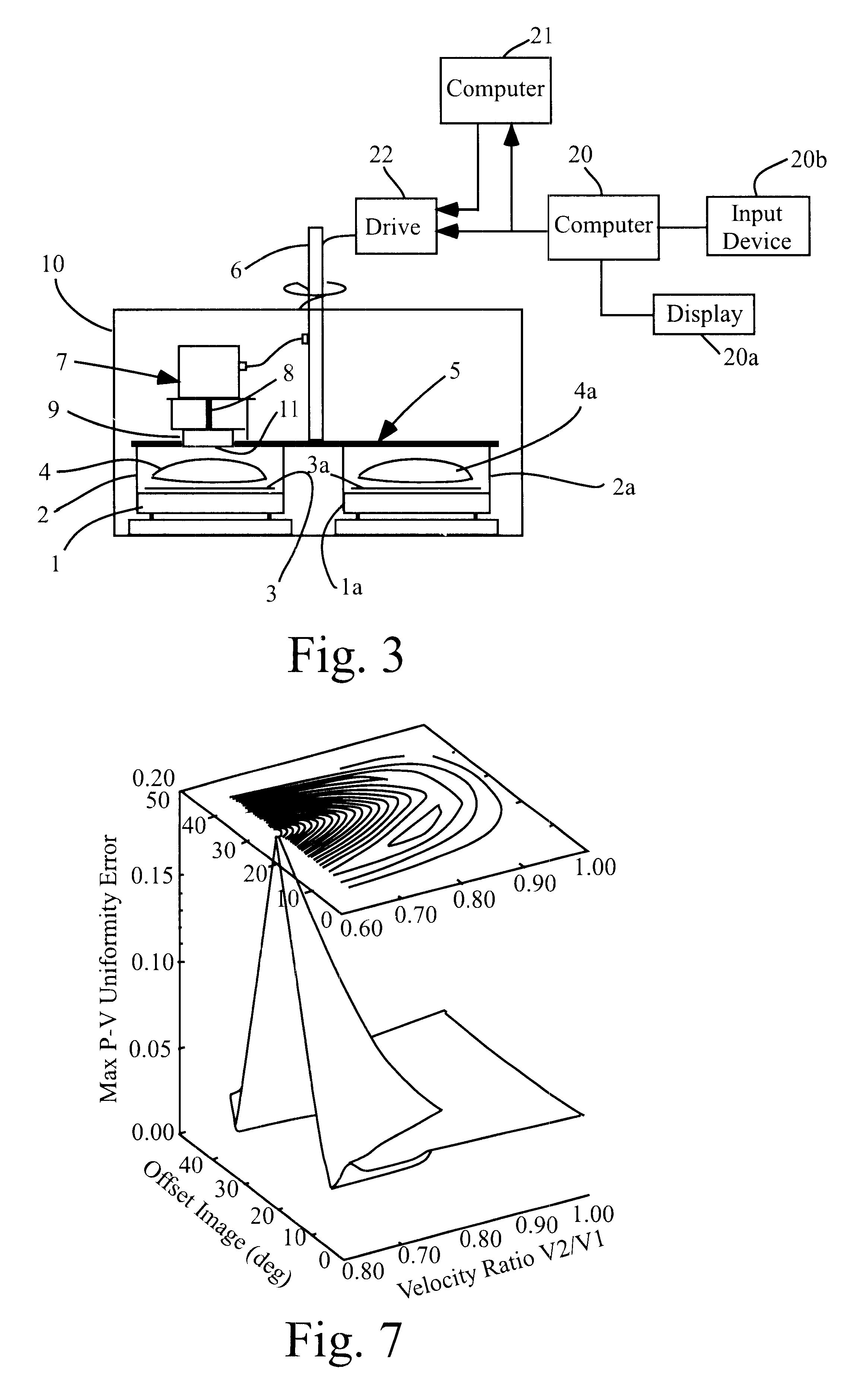
A first preferred embodiment of the invention will be described with reference to FIGS. 3-12. FIG. 3 is a cross-sectional view of a DC magnetron sputtering system which embodies the invention. The FIG. 3 system differs from that of FIGS. 1 and 2 only in that it includes: computer 20, which includes a display device 20A and an input device 20B (e.g. a mouse), and which is programmed to process measured flux distribution data (to be described) to generate predicted coating thickness profiles (each corresponding to a different selected substrate sweep velocity function) and to determine an optimal substrate sweep velocity function (for achieving a predet...


PUM

PropertyMeasurementUnit
pressureaaaaaaaaaa
diameteraaaaaaaaaa
sizeaaaaaaaaaa

Abstract

A method and system for producing a thin film with highly uniform (or highly accurate custom graded) thickness on a flat or graded substrate (such as concave or convex optics), by sweeping the substrate across a vapor deposition source with controlled (and generally, time-varying) velocity. In preferred embodiments, the method includes the steps of measuring the source flux distribution (using a test piece that is held stationary while exposed to the source), calculating a set of predicted film thickness profiles, each film thickness profile assuming the measured flux distribution and a different one of a set of sweep velocity modulation recipes, and determining from the predicted film thickness profiles a sweep velocity modulation recipe which is adequate to achieve a predetermined thickness profile. Aspects of the invention include a practical method of accurately measuring source flux distribution, and a computer-implemented method employing a graphical user interface to facilitate convenient selection of an optimal or nearly optimal sweep velocity modulation recipe to achieve a desired thickness profile on a substrate. Preferably, the computer implements an algorithm in which many sweep velocity function parameters (for example, the speed at which each substrate spins about its center as it sweeps across the source) can be varied or set to zero.

Description

1. Field of the InventionThe invention relates to methods and apparatus for producing thin films on substrates by vapor deposition (e.g., sputtering). The invention pertains to improving the accuracy of the deposited film thickness across the substrate (e.g., by improving the uniformity of the film thickness across the substrate where it is desired to deposit a film having uniform thickness).2. Discussion of the Related ArtThin film coatings are typically produced by various vapor deposition methods (such as sputtering, CVD, and electron beam evaporation) in which the substrate to be coated is passed through a vapor of the coating material and accumulates a thin film through condensation of the vapor. For many applications, such as optical films for EUV (extreme ultra violet) lithography, it is desirable that the coating be very uniform in thickness (e.g., with no more than 0.1% variation in thickness across the coated substrate). Multilayer coatings for EUV optics are commonly appl...

Claims


Application Information

Patent Timeline
Patent Type & Authority Patents(United States)
IPC IPC(8): C23C14/54G02B1/10
CPCC23C14/54G02B1/10C23C14/545C23C14/543
Inventor FOLTA, JAMES A.MONTCALM, CLAUDEWALTON, CHRISTOPHER
Owner EUV
Why Eureka
Try Eureka