Dry offset rotary printer for labeling wine corks

a technology of rotary printer and wine cork, which is applied in the direction of printing presses, office printing, printing, etc., can solve the problems of ineffective use of printing machines for printing indicia on natural cork stoppers and ineffective use of synthetic cork stoppers, so as to reduce the likelihood of damage and reduce the down time caused by corks not properly releasing from the print drum

Inactive Publication Date: 2003-03-04
APEX MACHINE
View PDF13 Cites 5 Cited by
  • Summary
  • Abstract
  • Description
  • Claims
  • Application Information

AI Technical Summary

Benefits of technology

to provide a printing machine capable of imprinting synthetic cork stoppers with little smearing.
One advantage to this system is that the silicone is applied to the cork during the printing process. Other methods require additional handling. In typical prior art processes, the printed corks are placed in a large tumbler, silicone is added to the tumbler and the mixture of corks and silicone tumbled for a suitable amount of time. By directly applying the silicone within the printing system the additional handling and time required are eliminated. Another prior art method of applying the silicone requires the silicone be sprayed onto the surface of the cork. This method involves an expensive spray system because of the very small quantity of silicone being applied. Spraying also requires some method of transferring the cork from the printing device to the spraying device without the possibility of silicone migrating back to the printing system. The silicone application station 600 described here eliminates these problems.

Problems solved by technology

However, the buying public typically perceives collapsible bags stored in boxes with exposed spigots and screw cap bottles as indicators of inferior quality wine.
This printing process is typically limited to single color printing.
Printing machines used for printing indicia on natural cork stoppers have been found to be ineffective when used with synthetic cork stoppers.

Method used


Image

  • Dry offset rotary printer for labeling wine corks
  • Dry offset rotary printer for labeling wine corks
  • Dry offset rotary printer for labeling wine corks

Examples


Embodiment Construction

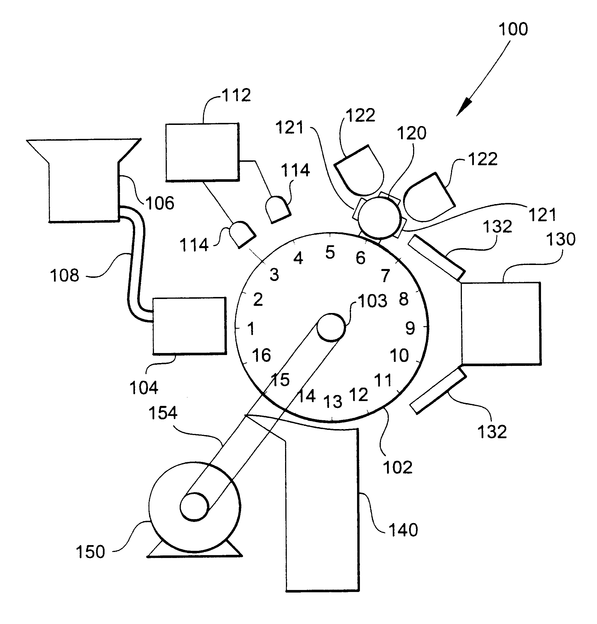
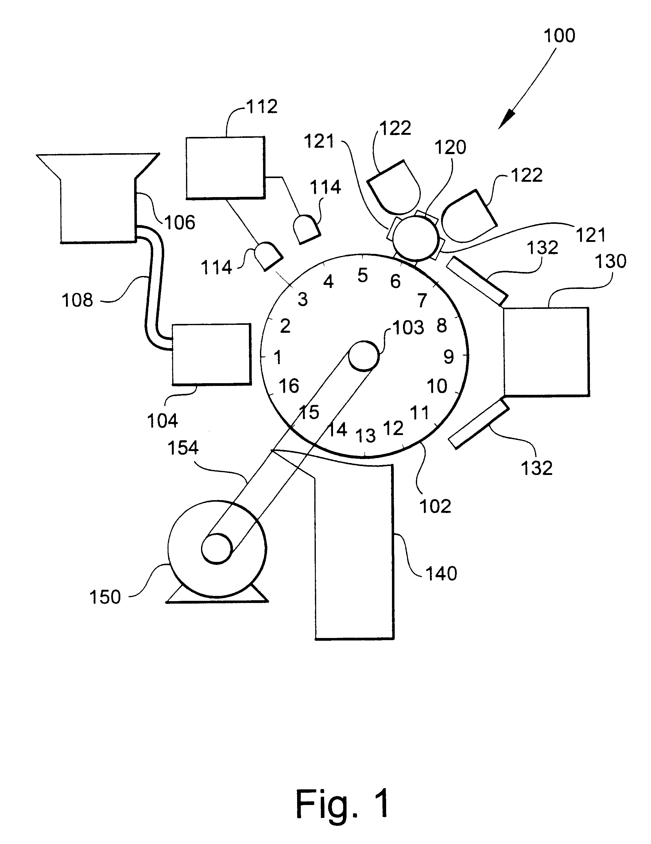
Referring now specifically to the drawings, a cork printer according to the present invention is illustrated in FIG. 1 and shown generally at reference numeral 100.

As used herein, the terms "cork," "corks," and "cork stopper" refer to synthetic and natural cork stoppers. Elements having the same or similar functions in the various Figures have similar reference numerals.

FIG. 1 illustrates a dry offset rotary printing machine 100 used for the printing of synthetic cork stoppers. The printing machine 100 comprises a rotatable Ferris wheel mechanism 102 having a plurality of evenly spaced carriers mounted a pre-determined radial distance from and parallel to the axis of rotation of Ferris wheel mechanism 102. Each carrier rotatably holds a synthetic cork stopper to be treated, printed and dried in the machine. Ferris wheel mechanism 102 illustrated in FIG. 1 has sixteen carrier positions, numbered 1 through 16. Each of these positions has a cork stopper carrier although it is not requi...


PUM


Abstract

A rotary printing machine for the printing of synthetic cork stoppers of the type having a surface which is normally non-ink receptive. A Ferris wheel mechanism is provided, having a plurality of evenly spaced carriers mounted a predetermined radial distance from and parallel to the axis of rotation for the Ferris wheel mechanism, each carrier for rotatably holding a synthetic cork stopper. An indexing drive system controls incremental rotation of the Ferris wheel mechanism through a predetermined sequence of steps, and a cork feeder introduces a single synthetic cork stopper into each of the carriers as empty ones of the carriers are presented one-by-one at the cork feeder. A corona discharger treats the surface of each synthetic cork stopper prior to being printed with sufficient energy to alter the surface energy of the cork sufficiently to permit receptivity of printing ink. A rotary printing system rotatably imprints with ink the surface of each held synthetic cork stopper with an image.

Description

TECHNICAL FIELD AND BACKGROUND OF THE INVENTIONThis invention relates to automated printing machines; and more particularly, to dry offset printing machines. As the demand for wine has increased, so has the demand for natural cork stoppers. To reduce demand for natural cork stoppers, containers other than bottles requiring cork stoppers, such as collapsible bags in boxes and bottles with screw cap lids, have been used. However, the buying public typically perceives collapsible bags stored in boxes with exposed spigots and screw cap bottles as indicators of inferior quality wine. To meet the demand for cork stoppers, synthetic cork stoppers have been developed. These synthetic cork stoppers are made from polymeric materials that have been extruded, or molded during a molding process. These synthetic corks have characteristics similar to their natural counterparts.In the wine industry, corks are frequently printed with words and other indicia identifying the vineyard where the wine wa...

Claims


Application Information

Patent Timeline
Patent Type & Authority Patents(United States)
IPC IPC(8): B41F17/08B41F17/22
CPCB41F17/22
Inventor CONINGSBY, GREGG O.
Owner APEX MACHINE
Why Eureka
Try Eureka