Scanning exposure method of direct-writing photoetching machine

A scanning exposure and lithography technology, applied in the field of scanning exposure, can solve the problems of long laser turn-on time, too long smear, overexposure, etc., to achieve the effect of improving exposure efficiency, avoiding stray light reflection, and avoiding overexposure

Active Publication Date: 2022-01-21
SUZHOU YUANZHUO OPTOELECTRONICS TECH CO LTD
View PDF7 Cites 0 Cited by
  • Summary
  • Abstract
  • Description
  • Claims
  • Application Information

AI Technical Summary

Problems solved by technology

However, it should be considered that in practical applications, for different exposure process requirements, whether the control of the laser is appropriate will directly affect the quality of the exposure pattern. The above-mentioned patent does not point out how to carry out precise control of the laser to synchronously cooperate with the digital micromirror device. And just turning off the laser when the DMD is switched also has the problem that the laser is turned on for too long, and there will still be "smear" and "overexposure" phenomenon, which will also cause energy waste

Method used


Image

  • Scanning exposure method of direct-writing photoetching machine
  • Scanning exposure method of direct-writing photoetching machine
  • Scanning exposure method of direct-writing photoetching machine

Examples


Embodiment Construction

[0023] In order to make the technical solution of the present invention more clear, the embodiments of the present invention will be described below in conjunction with the accompanying drawings. It should be understood that the specific descriptions of the embodiments are only used to teach those skilled in the art how to implement the present invention, rather than exhaustively listing all possible ways of the present invention, and not limiting the specific implementation scope of the present invention. Based on the embodiments of the present invention, all other embodiments obtained by persons of ordinary skill in the art without making creative efforts shall fall within the protection scope of the present invention.

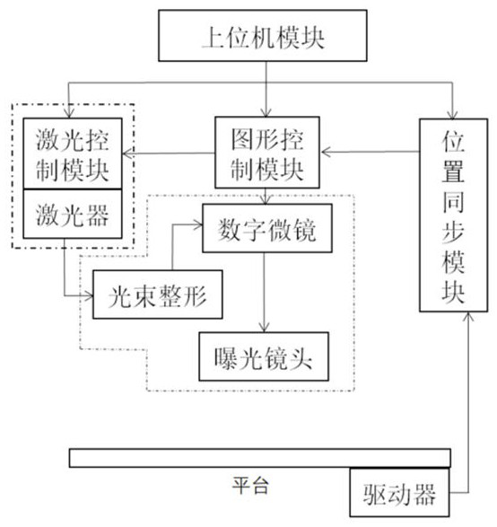
[0024] The schematic diagram of the direct-write lithography machine system module in the embodiment of the present invention is as follows figure 1 As shown, it mainly includes:

[0025] 1) The upper computer module is used to input external graphics files...


PUM


Abstract

The invention relates to a scanning exposure method of a direct-writing photoetching machine. The scanning exposure method specifically comprises the following steps that 1, a platform movement speed and laser process parameters are set by an upper computer module; 2, a platform driver drives the platform at a set speed and transmits a platform position signal to a position synchronization module; 3, the position synchronization module receives a platform position signal, processes the platform position signal and transmits the platform position signal to a graphic control module; 4, the graphic control module generates a synchronous control signal according to the received signal in combination with the platform movement speed and further transmits the synchronous control signal to the digital micro-mirror device and the laser control module, and the digital micro-mirror device completes graph state maintaining and switching of the micro-mirror array according to the synchronous control signal; and 5, the laser control module determines the duty ratio of a pulse control signal of the laser according to the laser process parameters and the graph refresh cycle so as to control the opening and closing of the laser according to the pulse control signal. According to the method, starting of the laser is accurately controlled through energy, and ''smear'' can be weakened under high-speed scanning.

Description

technical field [0001] The invention belongs to the field of direct-writing photolithography, and in particular relates to a scanning exposure method of a direct-writing photolithography machine. Background technique [0002] The laser direct writing lithography machine based on the digital micromirror device (DMD: Digital Micromirror Device) as the core component is widely used in the circuit production of PCB boards and semiconductor devices due to its simple process and low cost. The digital micromirror device is a micromirror array composed of a large number of tiny mirrors. The micromirror can be deflected at a fixed angle by controlling the micromirror with a digital voltage signal, thereby realizing the spatial modulation of the incident light. In the exposure process of the direct-write lithography machine, the laser is turned on to generate a beam, which is projected onto the substrate coated with photoresist through the modulation of the digital micromirror device,...

Claims


Application Information

Patent Timeline
Patent Type & Authority Applications(China)
IPC IPC(8): G03F7/20
CPCG03F7/70383G03F7/70425G03F7/70491G03F7/7055
Inventor 周黎张书荣胥涛棚李伟成张雷
Owner SUZHOU YUANZHUO OPTOELECTRONICS TECH CO LTD
Why Eureka
Try Eureka