Transmitting and receiving change-over switch for magnetic resonance system

A switching switch, magnetic resonance technology, applied in the direction of magnetic resonance measurement, etc., can solve the problems of inappropriateness, low isolation, and inability to accurately control when the signal receiving channel is opened, etc., to achieve the effect of high isolation

Pending Publication Date: 2021-06-22
SUZHOU NIUMAG ELECTRONICS TECH
View PDF0 Cites 4 Cited by
  • Summary
  • Abstract
  • Description
  • Claims
  • Application Information

AI Technical Summary

Problems solved by technology

It usually takes a while for the preamplifier to recover from saturation to linear amplification (as short as a few us to tens of us), which will lead to the extension of the receiving dead time, which is not suitable for some applications that have strict dead time requirements.
In addition to the disadvantage of low isolation, the passive T / R switch cannot precisely control when the signal receiving path is opened

Method used


Image

  • Transmitting and receiving change-over switch for magnetic resonance system
  • Transmitting and receiving change-over switch for magnetic resonance system
  • Transmitting and receiving change-over switch for magnetic resonance system

Examples


Embodiment

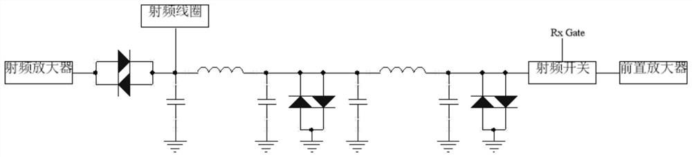
[0028] Embodiments of the present invention will be described in detail below in conjunction with examples. In this embodiment, a set of passive and active T / R switches is developed for a 21MHz low-field magnetic resonance analysis system. In order to improve the isolation, this embodiment adopts the scheme of connecting the second-level passive switch and the first-level active RF switch in series, such as Figure 5 shown. The first-stage passive switch consists of a PI filter circuit composed of L3, C26, and C27 and two diodes, D5 and D6. The second-stage passive switch consists of a PI filter circuit composed of L4, C28, and C29 and two diodes, D7 and D8. The active radio frequency switch selects the HSWA2-30DR+ of MiniCircuits Company. HSWA2-30DR+ is an absorptive RF switch with an internal drive circuit. Its insertion loss is relatively low, and its typical value is generally 0.75. At the same time it can also provide a high isolation of 64dB. RxGate is the receiving...


PUM


Abstract

The invention discloses a transmitting and receiving change-over switch for a magnetic resonance system, the magnetic resonance system comprises a radio frequency antenna, a transmitter and a receiver, wherein the transmitter and the receiver are respectively connected with the radio frequency antenna through a passive T/R switch. The magnetic resonance system is characterized in that an active radio frequency switch is connected in series between the passive T/R switch and the receiver, and the passive T/R switch adopts a two-stage passive T/R switch. The active radio frequency switch is controlled by a receiving gate control signal: in a radio frequency emission period, the receiving gate control signal is at a low level, and the active radio frequency switch is turned off; in the signal receiving period, the receiving gating signal is at a high level, the active radio frequency switch is turned on, and the receiving access is turned on. Compared with a traditional passive T/R switch, the switch formed by connecting the passive T/R switch and the active radio frequency switch in series can provide higher isolation for the pre-amplifier, and the situation that the pre-amplifier is damaged or saturated due to the fact that the isolation of the traditional T/R switch is not high is avoided.

Description

technical field [0001] The invention relates to the field of magnetic resonance, in particular to a transmitting and receiving switch for a magnetic resonance system. Background technique [0002] In the magnetic resonance system, a radio frequency coil with integrated transceiver is usually used. The coil with integrated transceiver has two working modes: transmitting working mode and receiving working mode. These two working modes are switched by the transmitting / receiving switch (T / R switch) of. Transmitting and receiving are carried out in time-sharing. During the pulse transmission stage, the radio frequency T / R switch opens the transmission channel in advance, and immediately turns off the transmission channel after the pulse transmission ends. After waiting for some time (i.e. dead time), the receiving channel is opened. The function of the T / R switch is to connect the RF coil and the transmitter during transmission, and send the RF power into the RF coil to ensure ...

Claims


Application Information

Patent Timeline
Patent Type & Authority Applications(China)
IPC IPC(8): G01R33/36
CPCG01R33/36
Inventor 杨培强沈杰
Owner SUZHOU NIUMAG ELECTRONICS TECH
Why Eureka
Try Eureka