Female terminal

Inactive Publication Date: 2003-03-04
JST MFG CO LTD
View PDF13 Cites 56 Cited by
  • Summary
  • Abstract
  • Description
  • Claims
  • Application Information

AI Technical Summary

Benefits of technology

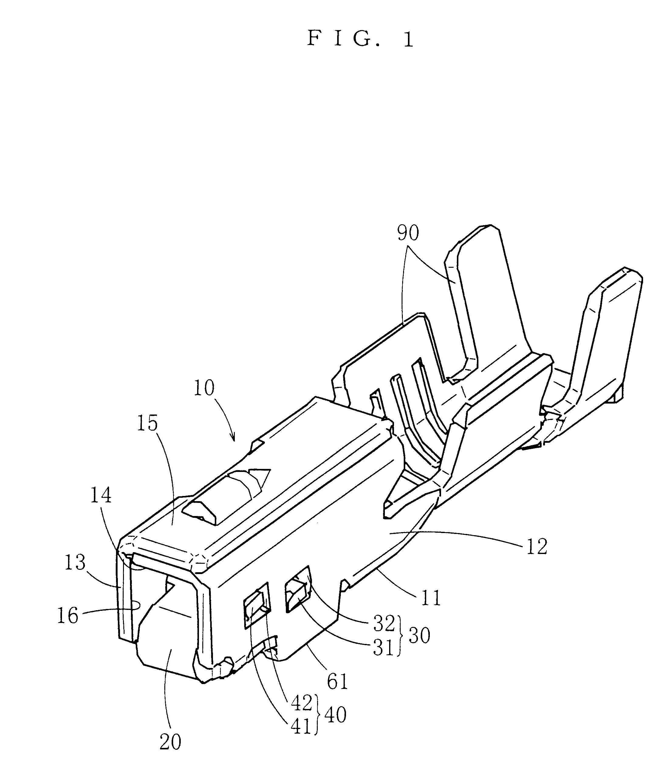
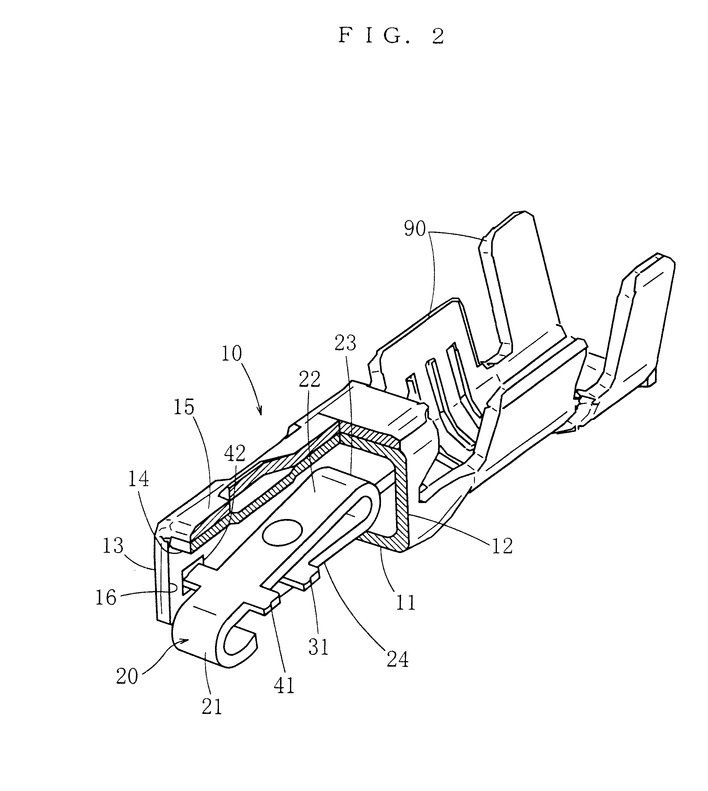
In the case of this female terminal, when it is inserted into a cell of a housing, a flexible piece will fit into the flexible-piece-receiving hole to fit the female terminal in the housing. If a male terminal is inserted through the front opening of the body, as the front end of the top end part of the leaf spring is fitted onto the side walls by the first fitting means, when the male terminal is inserted between the upper wall and the leaf spring and comes to the regular position, the leaf spring will exhibit its elastic restoring force for its elastic range between the front end of the top end part and the first bent part to provide an appropriate contact force between the male terminal and the leaf spring. If a prying force or the like acts, the second bent part of the leaf spring or the rear end of the top end part thereof will be displaced downward to contact the bottom wall, and in turn, the leaf spring will exhibit an elastic restoring force for an elastic range of only the intermediate part to balance the prying force or the like and prevent the leaf spring from excessive deformation. If the prying force or the like gets greater, the intermediate part of the leaf spring will be displaced downward to contact the top end part of the leaf spring, and in turn, the prying force or the like will be balanced by this contact and the leaf spring will be prevented from excessive deformation. If the prying force or the like increases much more, a part of the intermediate part ahead of the above-mentioned contact part of the intermediate part of the leaf spring will be displaced downward, and it will be stopped at a bottom dead point and fitted onto the side walls by the second fitting means. The prying force or the like will be balanced by this and the leaf spring will be prevented from excessive deformation. In this way, the prying force or the like is balanced in three stages to prevent the leaf spring from being deformed excessively.
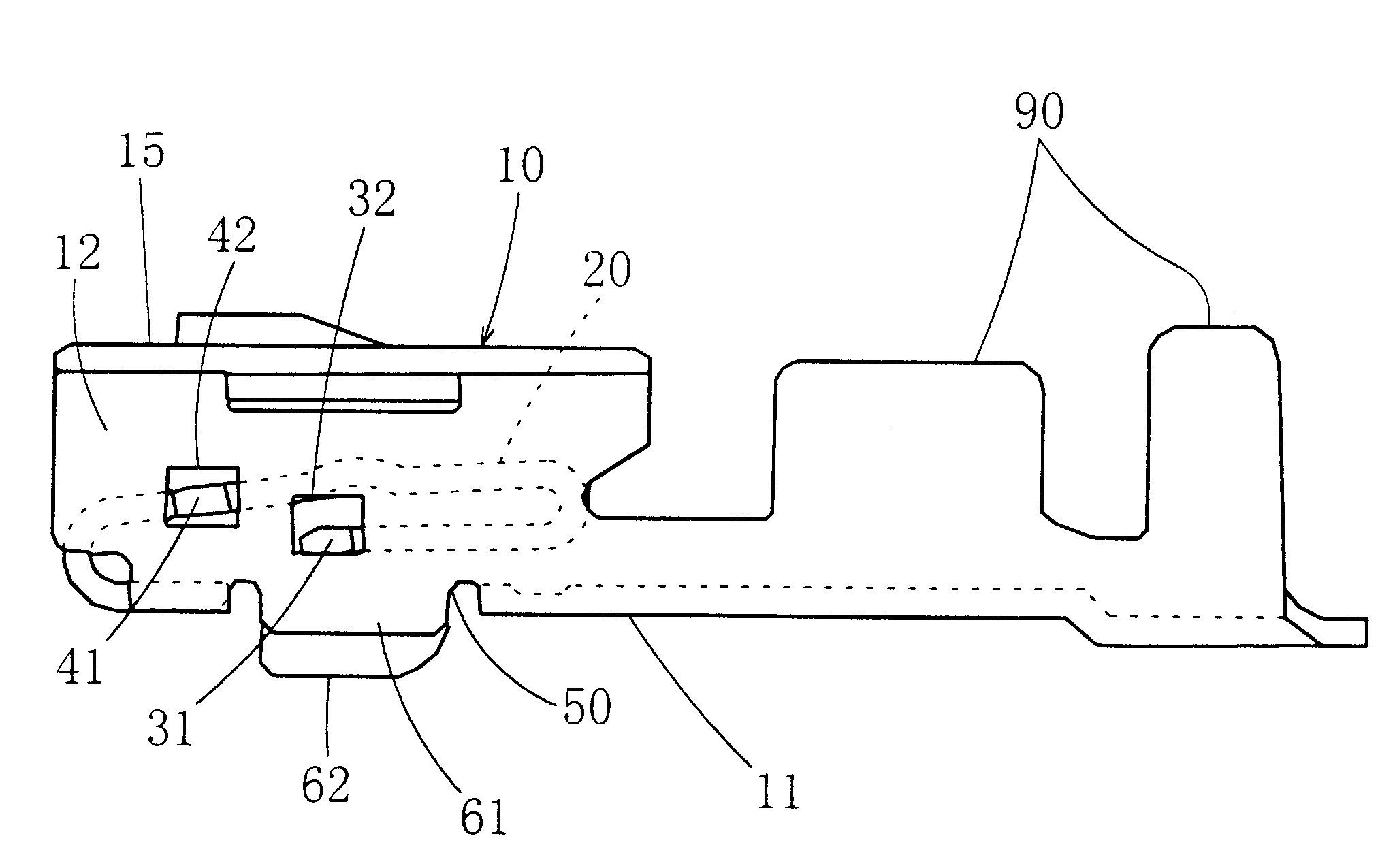
In this case, as the front end of the top end part of the leaf spring is fitted onto the side walls by the first fitting means, the part of the leaf spring to contact the bottom wall is the second bent part or the rear end of the top end part, in other words, a part around the rear end of the leaf spring. Moreover, as the intermediate part of the leaf spring is fitted onto the side walls by the second fitting means, a rising piece that was explained in the related art is not needed, and in turn, there is no need of securing a part, in the bottom wall, from which the rising piece is cut and raised. With these arrangements, a flexible-piece-receiving hole can be opened in the bottom wall between the first bent part of the leaf spring and the part the second bent part or the rear end of the top end part of the leaf spring contacts when it is displaced downward. As a result of this, the operation of disengaging the flexible piece from the female terminal can be done near the front end of the body. As the operation can be done under visual observation, the workability is improved. Moreover, as there is a space beneath the intermediate part of the leaf spring between the first bent part and the front end of the top end part, the height of the female terminal can be kept low by accommodating the flexible piece in this space. As a result, the female terminal can be compactified. Moreover, costs can be reduced through common use of metal molds for this female terminal and a female terminal without any flexible-piece-receiving hole made in the bottom wall thereof. Further, the elimination of the conventional rising pieces results in a more compact development of the female terminal, reduced number of bending processes, a reduced course of production, and improved precision of working.
To sum up, in the female terminal of the present invention the front end of the top end part of the leaf spring and a part of the intermediate part of the leaf spring ahead of the contact part of the intermediate part are fitted onto the side walls. As a result, the female terminal of the present invention provides an appropriate contact force between itself and a male terminal, prevents the leaf spring from being deformed excessively, enables opening a flexible-piece-receiving hole in the bottom wall, and in turn, allows operation of disengaging the flexible piece from the female terminal near the front end of the body, enables the operation under visual observation, and enhances the workability. Moreover, as the flexible piece can be accommodated in a space beneath the intermediate part of the leaf spring between the first bent part and the front end of the top end part, the female terminal can be compactified. Furthermore, through the common use of metal molds with a female terminal having no flexible-piece-receiving hole in the bottom wall, the costs can be reduced. Elimination of the conventional rising pieces results in a more compact development of the female terminal, a reduced number of bending processes, a shorter production process, and an improved accuracy of working.

Problems solved by technology

This, however, makes it inevitable that when the flexible piece is to be disengaged from the female terminal by means of a precision screwdriver or the like, one has to lift the flexible piece by inserting the precision screwdriver or the like deep into the cell.

Method used


Image

  • Female terminal
  • Female terminal
  • Female terminal

Examples


first embodiment

In the following, some embodiments of the present invention will be described with reference to the attached drawings. FIG. 1 through FIG. 3 show a female terminal of the

This female terminal comprises a tubular body 10, into which a male terminal 70 is inserted through a front opening 16, and a leaf spring 20 that is provided inside the body 10. The body 10 comprises a bottom wall 11, side walls 12, 13 that are provided on both ends of the bottom wall 11 in its width direction to oppose to each other, and upper walls 14, 15 that are provided on the upper sides of the side walls 12, 13 to oppose to the bottom wall 11. The opening 16 is formed at the front end by walls 11 through 15. In the case of this embodiment, the body 10 is formed by folding a sheet of plate. Thus the body 10 has the bottom wall 11, side walls 12, 13 rising from both ends of the bottom wall 11 in the width direction, and upper walls 14, 15 extending sidewise from the upper ends of the side walls 12, 13. The firs...

second embodiment

As is the case of the second embodiment, when the swelled parts 32, 42 are shifted in the vertical direction from the center of the height direction, a function of preventing reverse insertion is exhibited. The cell of the housing is provided with guide grooves extending inwardly on the inner walls of the cell. When the female terminal is to be inserted into the cell of the housing, the swelled parts 32, 42 are made to fit into these guide grooves. If the female terminal is inserted reversely, in other words, if the female terminal being kept upside down is incorrectly inserted into the cell, the swelled parts 32, 42 can not fit into the guide grooves, and the female terminal can not be inserted into the cell; thus reverse insertion is prevented.

The present invention includes all embodiments that combine features of the above-mentioned embodiments.

With the description of these embodiments, the first female terminal that was described in the summary of the invention was fully disclos...


PUM


Abstract

A female terminal includes: a tubular body; a leaf spring inside the body having a first bent part bent upward and rearward from the front end of the bottom wall of the body, an intermediate part extending rearward from the first bent part, a second bent part bent downward and forward from the rear end of the intermediate part, and a top end part extending forward from the second bent part and spaced away from the intermediate part; a first fitting means for fitting the front end of the top end part onto the side walls; a second fitting means, which allows the intermediate part to be displaced downward to contact the top end part of the leaf spring, and a part ahead thereof to be displaced downward until the intermediate part fits onto the side walls at the bottom dead point; and a flexible-piece-receiving hole in the bottom wall ahead of a part at which the leaf spring will contact the bottom wall.

Description

1. Field of the InventionThe present invention belongs to a technical field of female terminals to be fitted in a housing of a female connector, and relates to improvement of a female terminal, which has a leaf spring for contacting a male terminal, said leaf spring being provided inside a tubular body thereof.2. Related ArtA female terminal is known, which comprises a tubular body into which a male terminal is inserted through a front opening thereof and a leaf spring being provided inside the body. In the case of the female terminal that is disclosed by Japanese Patent unexamined publication gazette Heisei 9-147950, the body has a bottom wall, side walls that are provided on both ends of the bottom wall in its width direction to oppose to each other, and upper walls that are provided on the side walls on their upper side to oppose to the bottom wall. The leaf spring has a first bent part that is integrally provided on the front end of the bottom wall of the body and bends upward a...

Claims


Application Information

Patent Timeline
Patent Type & Authority Patents(United States)
IPC IPC(8): H01R13/187H01R13/15H01R13/11H01R13/115
CPCH01R13/187H01R13/114H01R13/11
Inventor CHEN, PING
Owner JST MFG CO LTD
Why Eureka
Try Eureka