Dual-polarized antenna

a dual-polarized antenna and antenna technology, applied in the direction of antennas, antenna details, antenna earthings, etc., can solve the problems of inability to achieve perfect isolation between feed ports in a dual-polarised antenna, inability to achieve good isolation between feed ports and undesired output ports,

Inactive Publication Date: 2003-03-11
TELEFON AB LM ERICSSON (PUBL)
View PDF17 Cites 67 Cited by
  • Summary
  • Abstract
  • Description
  • Claims
  • Application Information

AI Technical Summary

Problems solved by technology

Good isolation between feed ports is much more difficult to obtain in a dual-polarised antenna than in a pair of space diversity antennas as the latter are located a distance apart from each other.
Isolation between ports is never perfect in practice.
Isolation between feed ports is primarily a problem on tranmit while coupling between feed ports and undesired output ports is primarily a problem on receive.
This is achieved with filters, and the worse the mutual coupling between feed ports the worse the leakage and the better the filters have to be.
Better filters, which give better suppression, are as a rule more expensive and unwieldy.
Mutual coupling between feed ports can also cause problems when the transmitted signal from one port travels "backwards" via the other transmit branch.
This may give rise to intermodulation effects and spurious radiation, both in the uplink and downlink frequency bands.
Coupling between a feed port and undesirable output port will result in polarisation impurities.
On receive the impurities may increase the correlation between the received signals, which in turn diminishes the diversity gain potential.
There are a number of factors that adversely affect the polarisation purity and the mutual coupling of an antenna.
While this arrangement is truly symmetric, it is not useful for communication applications for a number of reasons.
This solution can only be used to obtain a two-port antenna element with good isolation properties at one or a few frequencies.
Nor does the design allow for simultaneous symmetrical slot feed for both polarisation ports.

Method used


Image

  • Dual-polarized antenna
  • Dual-polarized antenna
  • Dual-polarized antenna

Examples


Embodiment Construction

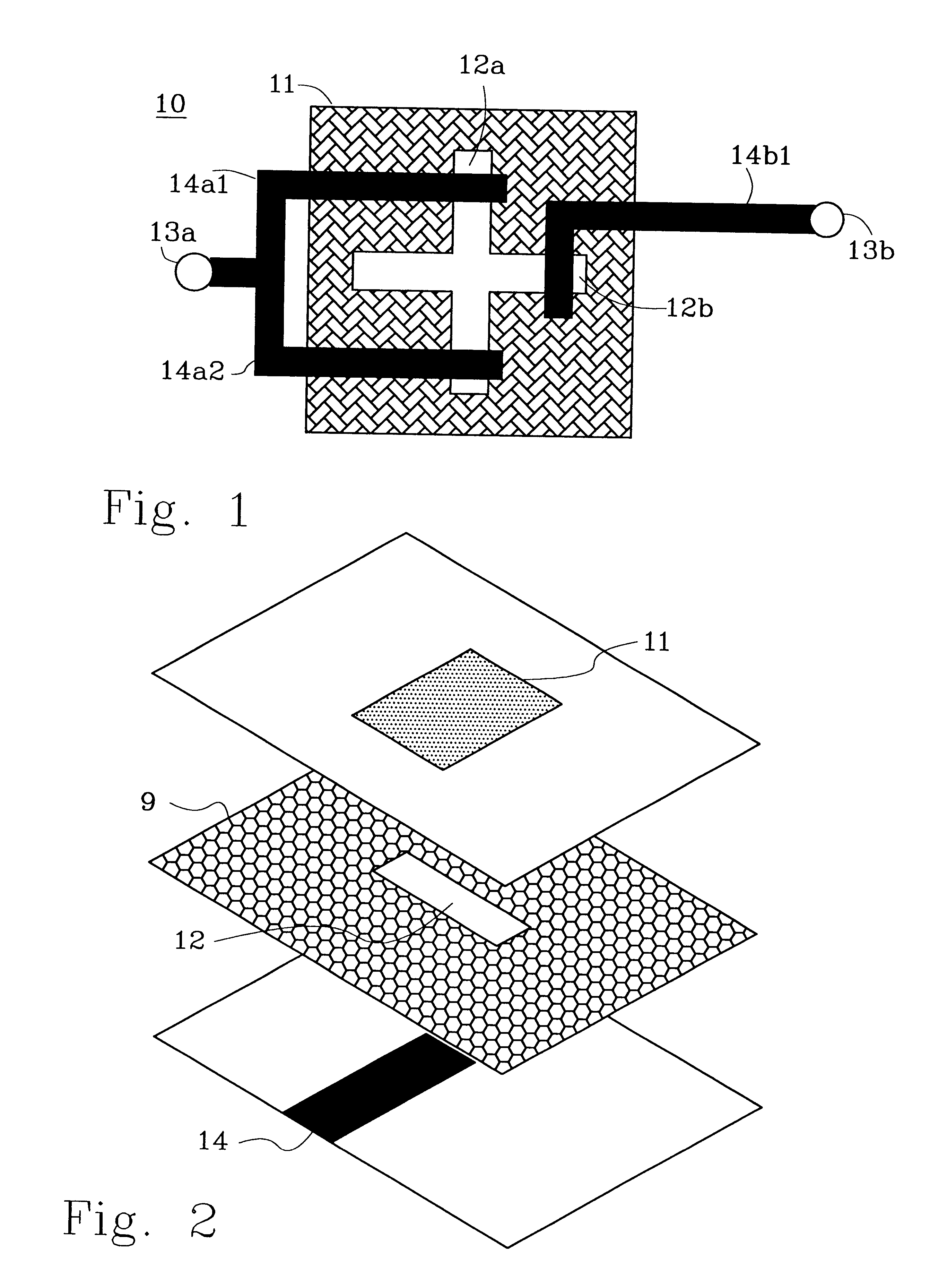
FIG. 1 shows an example of a prior art dual-polarised microstrip antenna (WO 98 / 49741). An antenna element 10 comprises a patch 11 and two orthogonal slots 12a, 12b as feed structures. Two ports 13a, 13b--one for each polarisation--are the sources for the feed network 14. Port 13a is connected to network part 14a that bifurcates into branches 14a1 and 14a2. Each of these branches 14a1, 14a2 cross the vertical slot 12a, one on each side of slot 12b. Port 13b on the other hand is connected to another network part 14b1. This second network part 14b1 intersects slot 12b.

As can be seen from FIG. 1, slot 12b is not fed symmetrically. The design does not allow for simultaneous symmetrical slot feed for both polarisation ports. This leads to polarisation impurities.

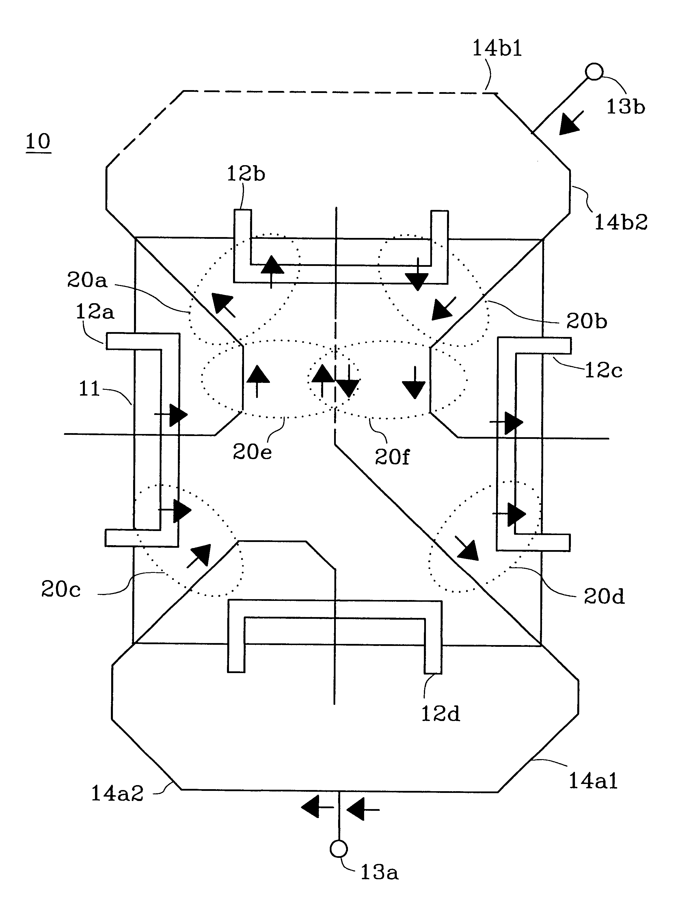
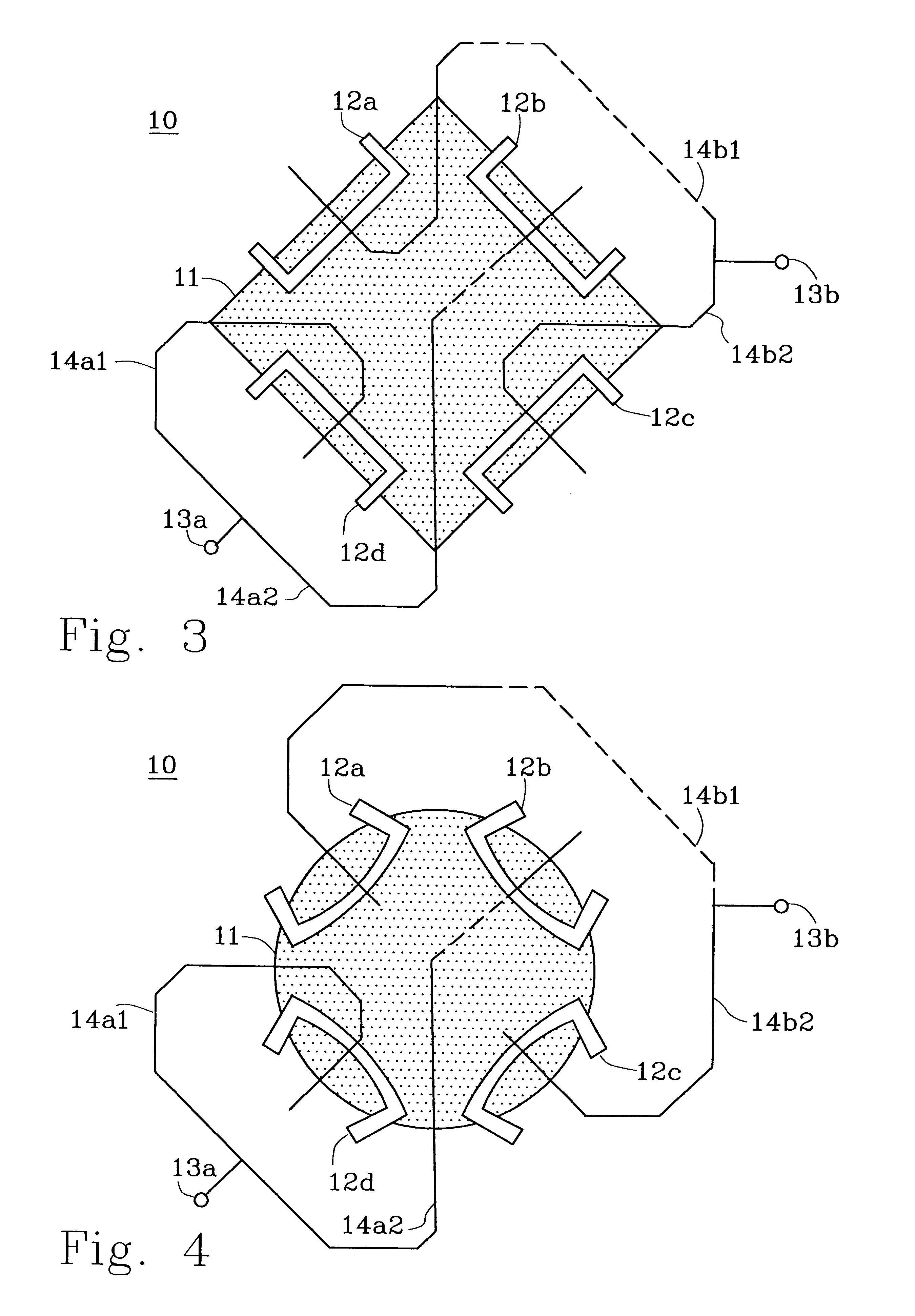
One way of improving port isolation is to arrange and exploit symmetries in the feed network. The resulting current symmetries will also generate similar patterns for the two orthogonal polarisations.

A first concern when designin...


PUM


Abstract

A dual-polarized antenna (10) with good isolation between feed ports (13a, 13b) and high similarity with respect to the radiation patterns is provided. An antenna (10) includes a patch (11), four symmetrically arranged feed structures (12a-12d, 15), two feed ports (13, 13b) and a feed network (14). Radiation pattern similarity is obtained by the pair-wise symmetrical, orthogonal layout of the feed structures (12a-12d, 15). Good isolation between feed ports (13a, 13b) is achieved through a feed network (14) divided into two network parts (14a, 14b) where each network part (14a, 14b) is designed so that each coupling between a network part (14a, 14b) and a feed structure (12a12d, 15) belonging to the other polarization is cancelled by a mirrored coupling with the other feed structure (12a-12d, 15) belonging to the polarization. In addition, a network part (14a, 14b) is laid out so that its corresponding feed structures (12a-12d, 15) are fed with supporting signals of equal magnitude.

Description

This application claims priority under 35 U.S.C. .sctn..sctn.119 and / or 365 to 9903920-8 filed in Sweden on Oct. 29, 1999; the entire content of which is hereby incorporated by reference.This invention relates to the technical field of antennas, and more specifically to dual-polarised antennas.DESCRIPTION OF RELATED ARTHistorically, the most common diversity technique, especially in mobile communications, has been space diversity. In this diversity technique two or more antennas are placed apart from each other, separated by a distance that is a function of the wavelength the antennas should receive or transmit. On uplink the incoming signals received at each antenna are combined in an optimum way so as to maximise the quality of the resulting signal.Owing to economical as well as aesthetical reasons, base stations are nowadays increasingly equipped with a single dual-polarised antenna, or one such antenna for each sector or frequency band. Such an antenna must provide two at least ...

Claims


Application Information

Patent Timeline
Patent Type & Authority Patents(United States)
IPC IPC(8): H01Q1/38H01Q9/04
CPCH01Q9/0435H01Q1/38
Inventor JOHANNISSON, BJORNDERNERYD, ANDERSJOHANSSON, MARTIN
Owner TELEFON AB LM ERICSSON (PUBL)
Why Eureka
Try Eureka