

ATV transmission
a transmission and atv technology, applied in the direction of couplings, cycle equipments, gears, etc., can solve the problems of increasing the crossing angle, reducing the service life of the joint,
- Summary
- Abstract
- Description
- Claims
- Application Information
AI Technical Summary
Benefits of technology
Problems solved by technology
Method used
Image

Examples
Embodiment Construction
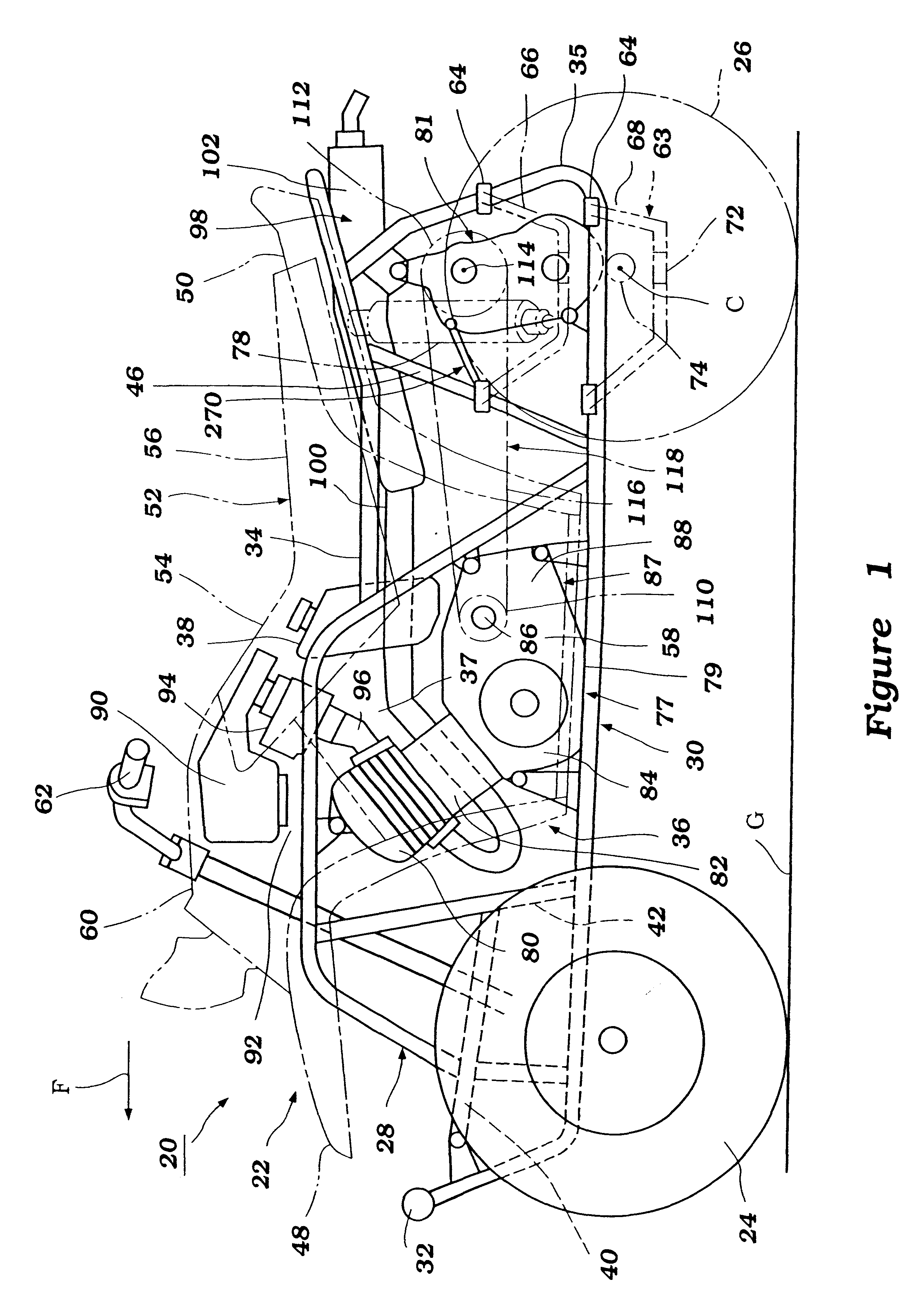
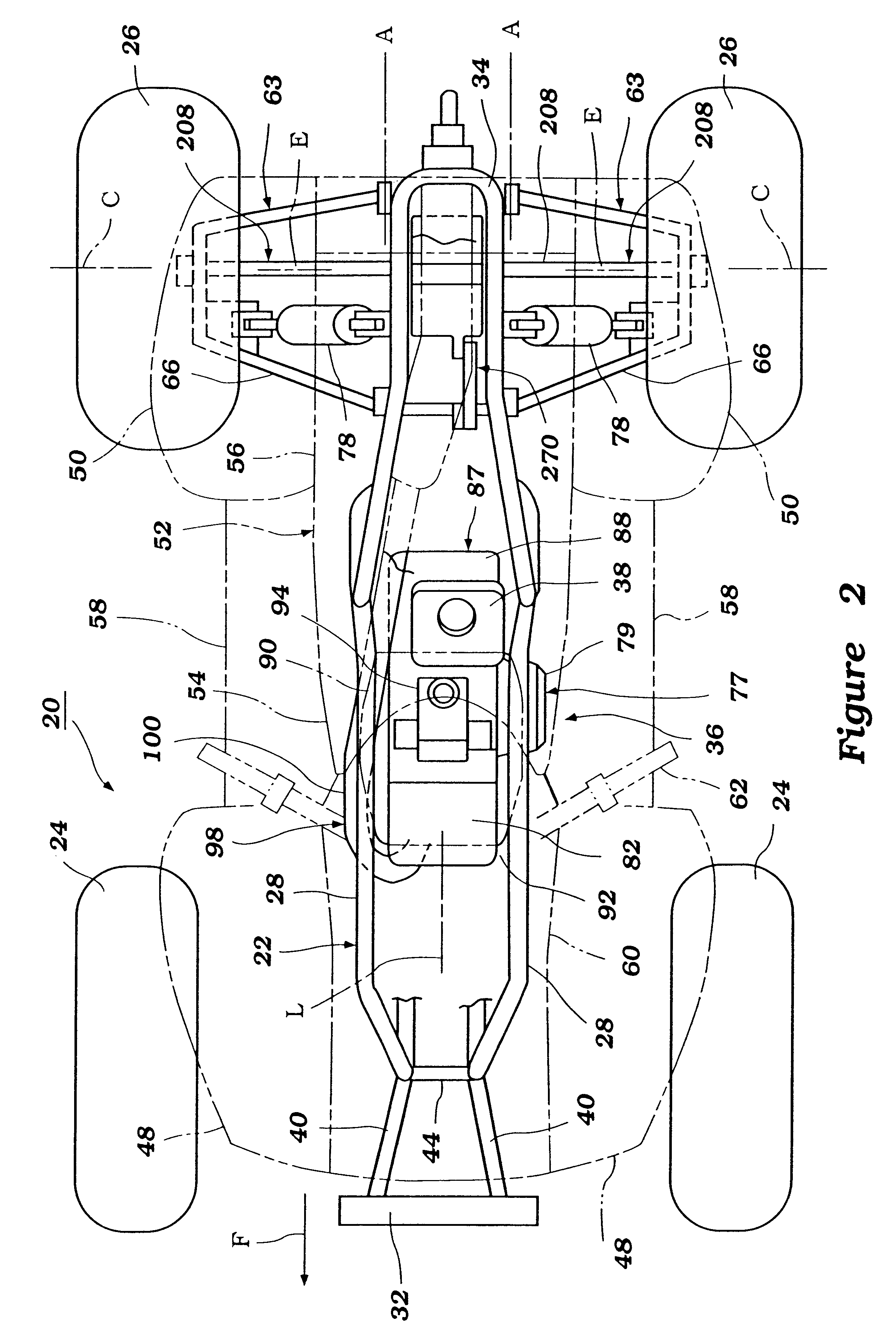
With reference now to FIGS. 1 through 3, an all terrain vehicle is illustrated and is generally identified by the reference numeral 20. The vehicle 20 incorporates a transmission that is arranged and configured in accordance with certain features, aspects and advantages of the present invention. The illustrated vehicle 20 preferably is adapted for off-road operation; however, certain features, aspects and advantages that will become apparent below can be used in street vehicles. In addition, as the illustrated vehicle 20 is only a typical application for the present invention, other applications will become readily apparent to those of ordinary skill in the art. For this reason, many details of the illustrated vehicle 20 that do not require an understanding for one of ordinary skill in the art to practice the present invention will be omitted; however, the omitted details should be considered well-known to those of ordinary skill in the art.
With continued reference to FIG. 1, the ve...
PUM
 Abstract
Description
Claims
Application Information